
User Manual


AFL2-W10A-N28 Panel PC
Page 127
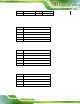
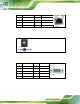
7.2.25 Webcam Connector (CAMERA1)
PIN NO. DESCRIPTION
1 VCC
2 -DATA6
3 +DATA6
4 GND
Table 7-26: Webcam Connector (CAMERA1) Pin outs
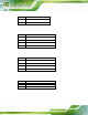
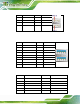
7.2.26 Webcam Microphone Connector (WEBCAM_DMIC1)
PIN NO. DESCRIPTION
1 DMIC_CLK_R
2 DMIC_DATA_R
3 VCC
4 GND
Table 7-27: Webcam Microphone Connector (WEBCAM_DMIC1) Pinouts
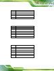
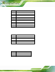
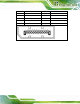
7.3 External Interface Panel Connectors
The table below lists the rear pan el connectors on the AFL2MB-1 5A motherboard. Pinouts
of these connectors can be found in the following se ctions.
Connector Type Label
DisplayPort connector DisplayPort DISPLAY_PORT1
Ethernet connector RJ-45 JP6
Power connector Power jack DC_IN1
RS-232 serial port DB-9 COM1
RS-232 serial port RJ-45 COM3
RS-422/485 serial port RJ-45 COM2
USB 2.0 connectors USB 2.0 port USB1
USB 3.0 connectors USB 3.0 port USB3_1
Table 7-28: Rear Panel Connectors