
User guide

AFL2-17A/AB-H61
Page 76
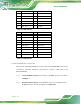
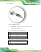
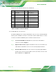
The pinouts of the USB 3.0 connectors are shown below.
Step 1:
Pin Description Pin Description
1 USB3_PWR1 2 USB2P0_DM1_L
3 USB2P0_DP1_L 4 GND
5 USB3P0_RXDN1_L 6 USB3P0_RXDP1_L
7 GND 8 USB3P0_TXDN1_C_L
9 USB3P0_TXDP1_C_L 10 USB3_PWR2
11 USB2P0_DM2_L 12 USB2P0_DP2_L
13 GND 14 USB3P0_RXDN2_L
15 USB3P0_RXDP2_L 16 GND
17 USB3P0_TXDN2_C_L 18 USB3P0_TXDP2_C_L
Table 5-8: USB 3.0 connectors Pinouts
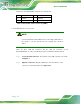
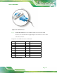
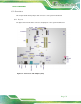
5.14.6 VGA Monitor Connection
The AFL2-17A/AB-H61 has a single female DB-15 connector on the external peripheral
interface panel. The DB-15 connector is connected to a CRT or VGA monitor. To connect
a monitor to the AFL2-17A/AB-H61, please follow the instructions below.
Step 1: Locate the female DB-15 connector. The location of the female DB-15
connector is shown in Chapter 1.
Step 2: Align the VGA connector. Align the male DB-15 connector on the VGA screen
cable with the female DB-15 connector on the external peripheral interface.
Step 3: Insert the VGA connector. Once the connectors are properly aligned with the
insert the male connector from the VGA screen into the female connector on the
AFL2-17A/AB-H61. See Figure 5-28.