
User guide

AFL2-17A/AB-H61
Page 75
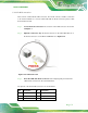
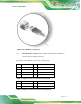
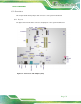
Figure 5-27: USB Device Connection
Step 3: Insert the device connector. Once aligned, gently insert the USB device
connector into the onboard connector. Step 0:
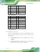
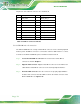
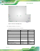
The pinouts of the USB 2.0 connectors are shown below.
Pin Description Pin Description
1 POWER 2 -DATA0
3 +DATA0 4 GND
5 POWER 6 -DATA1
7 +DATA1 8 GND
Table 5-6: USB 2.0 connectors Pinouts (bottom panel)
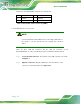
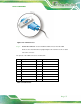
Pin Description Pin Description
1 POWER 2 -DATA2
3 +DATA2 4 USB20_GND
Table 5-7: USB 2.0 connectors Pinouts (left side panel)