
User Manual

AFL2-17A/AB-H61
Page 64
5.13.3 Stand Mounting
To mount the AFL2-17A/AB-H61 using the stand mounting kit, please follow the steps
below.
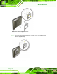
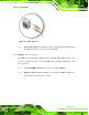
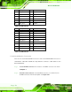
Step 1: Locate the screw holes on the rear of the AFL2-17A/AB-H61. This is where the
bracket will be attached. (Figure 5-20)
Figure 5-20: Mounting screw location
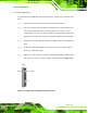
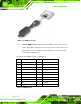
Step 2: Align the bracket with the screw holes.
Step 3: To secure the bracket to the AFL2-17A/AB-H61, insert the retention screws into
the screw holes and tighten them. Step 0:
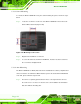
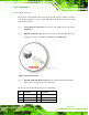
5.13.4 Arm Mounting
The AFL2-17A/AB-H61 is VESA (Video Electronics Standards Association) compliant and
can be mounted on an arm with a 100mm interface pad. To mount the AFL2-17A/AB-H61
on an arm, please follow the steps below.
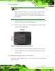
Step 1: The arm is a separately purchased item. Please correctly mount the arm onto
the surface it uses as a base. To do this, refer to the installation documentation
that came with the mounting arm.