
Manual

AFL2-17A/AB-H61
Page 66
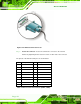
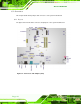
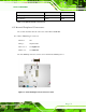
Figure 5-27: VGA Connector
Step 4: Secure the connector. Secure the DB-15 VGA connector from the VGA
monitor to the external interface by tightening the two retention screws on either
side of the connector.
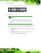
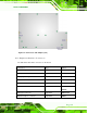
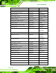
The pinouts of the VGA connector is shown below.
Pin Description Pin Description
1 CRT_RED 2 CRT_GREEN
3 CRT_BLUE 4 NC
5 GND 6 GND
7 GND 8 GND
9 CRT_VCC 10 CRT_PLUG#
11 NC 12 CRT_DDC_DATA
13 CRT_HSYNC 14 CRT_VSYNC
15 CRT_DDC_CLK
Table 5-9: VGA Pinouts