
Manual

AFL2-17A/AB-H61
Page 61
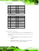
Pin Description Pin Description
7 LAN1_MDI2+ 8 LAN1_MDI2-
9 LAN1_MDI3+ 10 LAN1_MDI3-
11 GND 12 GND
13 NC 14 NC
L1 LAN1_LINK100 L2 LAN1_LINK1000
L3 LAN1_ACT-1 L4 POWER
Table 5-2: LAN1 Pinouts
Pin Description Pin Description
1 LAN2_MDI0+ 2 LAN2_MDI0-
3 LAN2_MDI1+ 4 LAN2_MDI1-
5 GND 6 GND
7 LAN12_MDI2+ 8 LAN2_MDI2-
9 LAN2_MDI3+ 10 LAN2_MDI3-
11 GND 12 GND
13 NC 14 NC
L1 LAN12_LINK100 L2 LAN2_LINK1000
L3 LAN2_ACT-1 L4 POWER
Table 5-3: LAN2 Pinouts
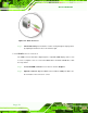
5.14.4 Serial Device Connection
There are two external RS-232 DB-9 connectors and one RS-422/485 DB-9 connector for
serial device connection. Follow the steps below to connect a serial device to the
AFL2-17A/AB-H61.
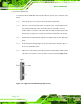
Step 1: Locate the DB-9 connector. The locations of the DB-9 connectors are shown
in Chapter 1.
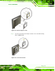
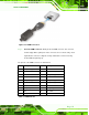
Step 2: Insert the serial connector. Insert the DB-9 connector of a serial device into
the DB-9 connector on the bottom panel. See Figure 5-25.