
Manual

AFL2-12A-HM65 Series Panel PC
Page 71
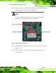
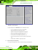
Step 11: Connect the main (1) and auxiliary (2) antennas. The main antenna is indicated
with a strip of black electrical tape. See Figure
ٛ 5-7.
NOTE:
To ensure the WLAN module functions correctly, please make sure the
WLAN antennas are attached in the proper configuration.
Figureٛ 5-7: Attaching the Antennas
Step 12: Replace the internal aluminum cover and secure it to the chassis using six (6)
retention screws.
Step 13: Replace the back cover and secure it using nine (9) previously removed
retention screws. Step 0: