
Manual


AFL2-12A-HM65 Series Panel PC
Page 59
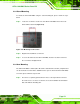
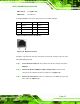
Pin RS-422 RS-485
1 RX+
2 RX-
3 TX+ DATA+
4 TX- DATA-
Table 4-2: RS-422/485 Serial Port Pinouts
To install the RS-422/485 devices, follow the steps below.
Step 1: Locate the RS-422/RS485 connector. The location of the RS-422/RS-485
connector is shown in Figure 1-6.
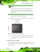
Step 2: Conn
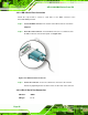
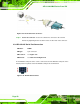
ect the RS-422/485 connector to the RS-422/485 cable. The
RS-422/485 cable can be found in the packing list and is shown in Figure 4-20.
Figure 4-20: RS-422/485 Cable
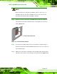
Step 3: Insert the serial connector. Insert the DB-9 connector of a serial device into
the DB-9 connector on the RS-422/485 cable.
Step 4: Secure the connector. Secure the serial device connector to the external
interface by tightening the two retention screws on either side of the connector.
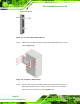
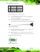
The DB-9 connector pinouts are listed below. Step 0:
Figure 4-21: DB-9 Connector