
Manual
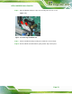
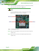


Table Of Contents
- 1 Introduction
- 2 Detailed Specifications
- 3 Unpacking
- 4 Installation
- 5 System Maintenance
- 6 AMI BIOS Setup
- 7 Software Drivers
- A Safety Precautions
- B BIOS Configuration Options
- C One Key Recovery
- D Watchdog Timer
- E Hazardous Materials Disclosure
AFL2-12A-D525 Series Panel PC
Page 72
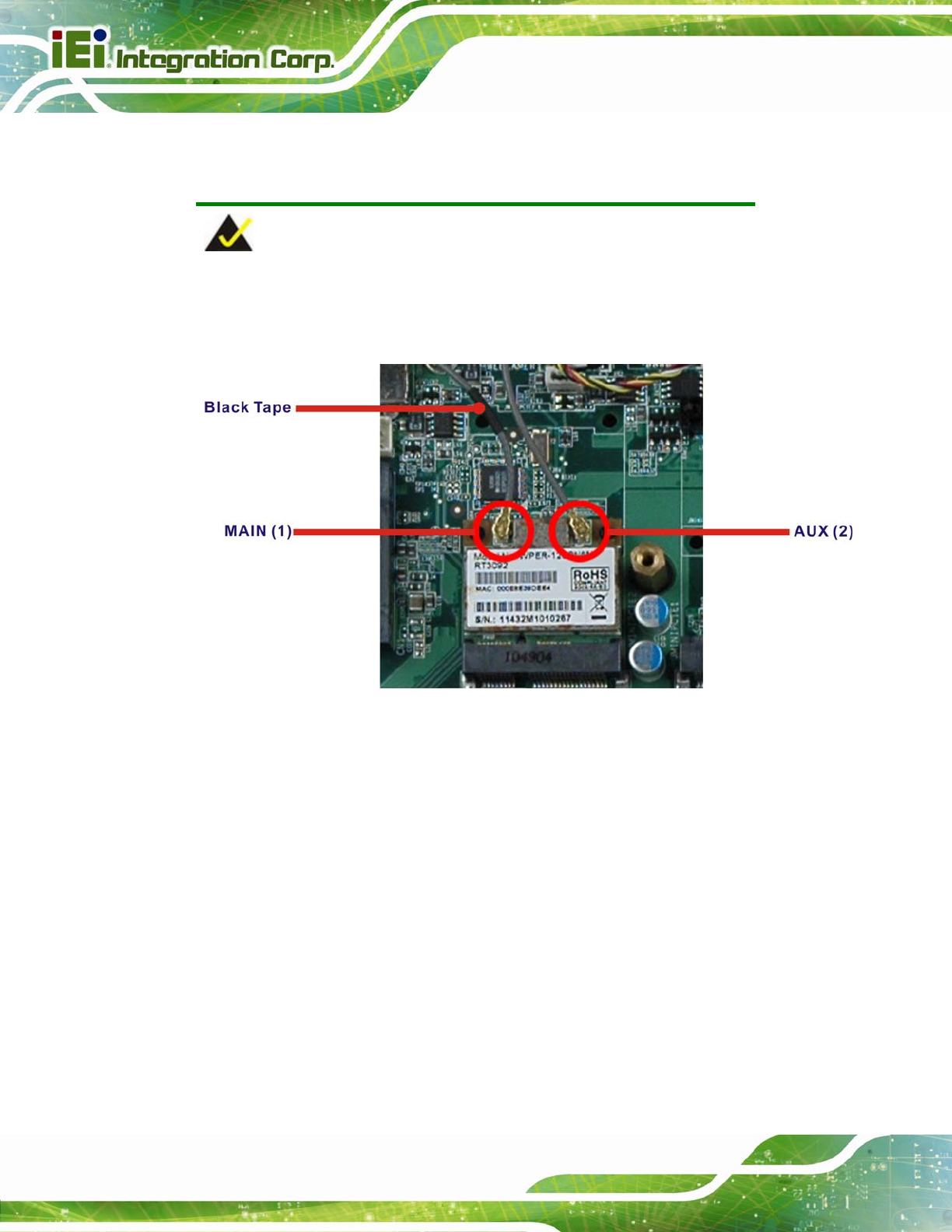
Step 11: Connect the main (1) and auxiliary (2) antennas. The main antenna is indicated
with a strip of black electrical tape. See
Figureٛ 5-7.
NOTE:
To ensure the WLAN module functions correctly, please make sure the
WLAN antennas are attached in the proper configuration.
Figureٛ 5-7: Attaching the Antennas
Step 12: Replace the internal aluminum cover and secure it to the chassis using six (6)
retention screws.
Step 13: Replace the back cover and secure it using nine (9) previously removed
retention screws. Step 0: