
Manual
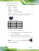
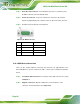


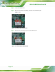
Table Of Contents
- 1 Introduction
- 2 Detailed Specifications
- 3 Unpacking
- 4 Installation
- 5 System Maintenance
- 6 AMI BIOS Setup
- 7 Software Drivers
- A Safety Precautions
- B BIOS Configuration Options
- C One Key Recovery
- D Watchdog Timer
- E Hazardous Materials Disclosure
AFL2-12A-D525 Series Panel PC
Page 62
Step 3: Insert the serial connector. Insert the DB-9 connector of a serial device into
the DB-9 connector on the RS-422/485 cable.
Step 4: Secure the connector. Secure the serial device connector to the external
interface by tightening the two retention screws on either side of the connector.
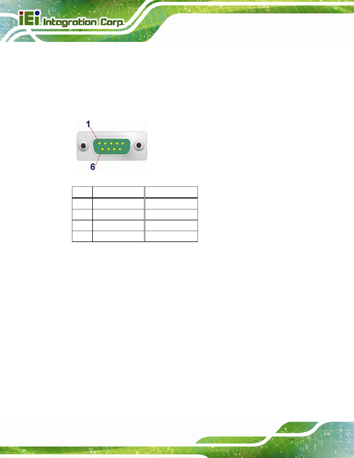
Step 5: The DB-9 connector pinouts are listed below.
Figure 4-25: DB-9 Connector
Pin RS-422 RS-485
1 TX- DATA-
2 TX+ DATA+
3 RX+
4 RX-
Table 4-4: DB-9 Connector Pinouts
Step 0:
4.10.4 USB Device Connection
There are two external USB 2.0 connectors. All connectors are perpendicular to the
AFL2-12A-D525. To connect a USB 2.0 or USB 1.1 device, please follow the instructions
below.
Step 1: Located the USB connectors. The locations of the USB connectors are shown
in Chapter 2.
Step 2: Align the connectors. Align the USB device connector with one of the
connectors on the bottom panel. See
Figure 4-26.