
Manual
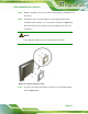
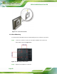

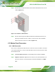


Table Of Contents
- 1 Introduction
- 2 Detailed Specifications
- 3 Unpacking
- 4 Installation
- 5 System Maintenance
- 6 AMI BIOS Setup
- 7 Software Drivers
- A Safety Precautions
- B BIOS Configuration Options
- C One Key Recovery
- D Watchdog Timer
- E Hazardous Materials Disclosure
AFL2-12A-D525 Series Panel PC
Page 59
Figure 4-20: DB-9 Serial Port Connector
Step 3: Secure the connector. Secure the serial device connector to the external
interface by tightening the two retention screws on either side of the connector.
Step 0:
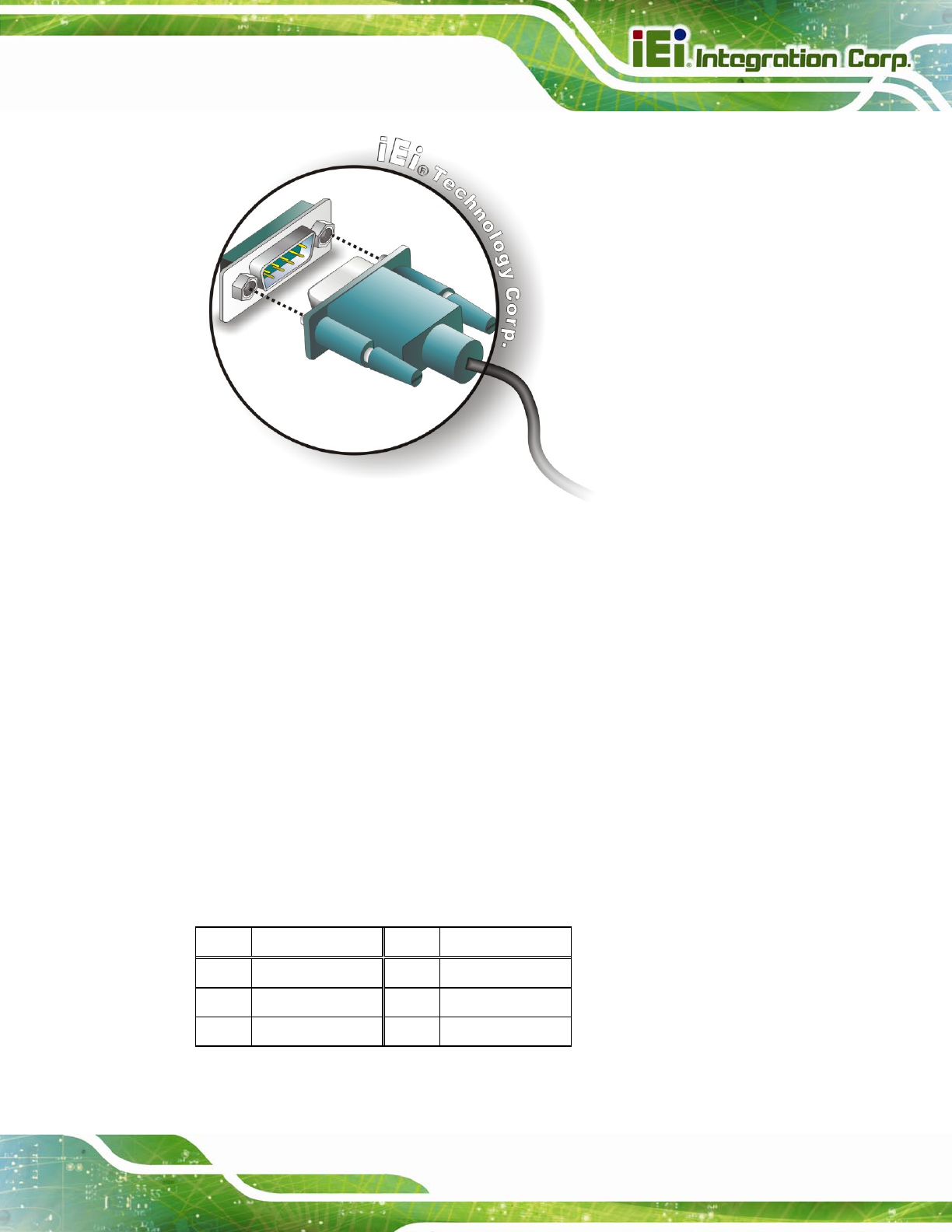
4.10.2.2 RJ-45 Serial Port Connection
CN Label: COM3
CN Type:
RJ-45
CN Location:
See
Figure 4-21
CN Pinouts:
See
Table 4-2
A 10/100/1000 Mb/s connection can be made to a Local Area Network.
Pin Description Pin Description
1 DCD3 5 TXD3
2 DSR3 6 CTS3
3 RXD3 7 DTR3