
Manual
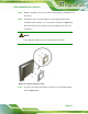
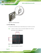

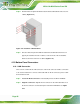


Table Of Contents
- 1 Introduction
- 2 Detailed Specifications
- 3 Unpacking
- 4 Installation
- 5 System Maintenance
- 6 AMI BIOS Setup
- 7 Software Drivers
- A Safety Precautions
- B BIOS Configuration Options
- C One Key Recovery
- D Watchdog Timer
- E Hazardous Materials Disclosure
AFL2-12A-D525 Series Panel PC
Page 58
Figure 4-19: DB-9 Connector
Pin Description Pin Description
1 DCD1 2 RX1
3 TX1 4 DTR1
5 GND 6 DSR1
7 RTS1 8 CTS1
9 RI1
Table 4-1: DB-9 Connector Pinouts
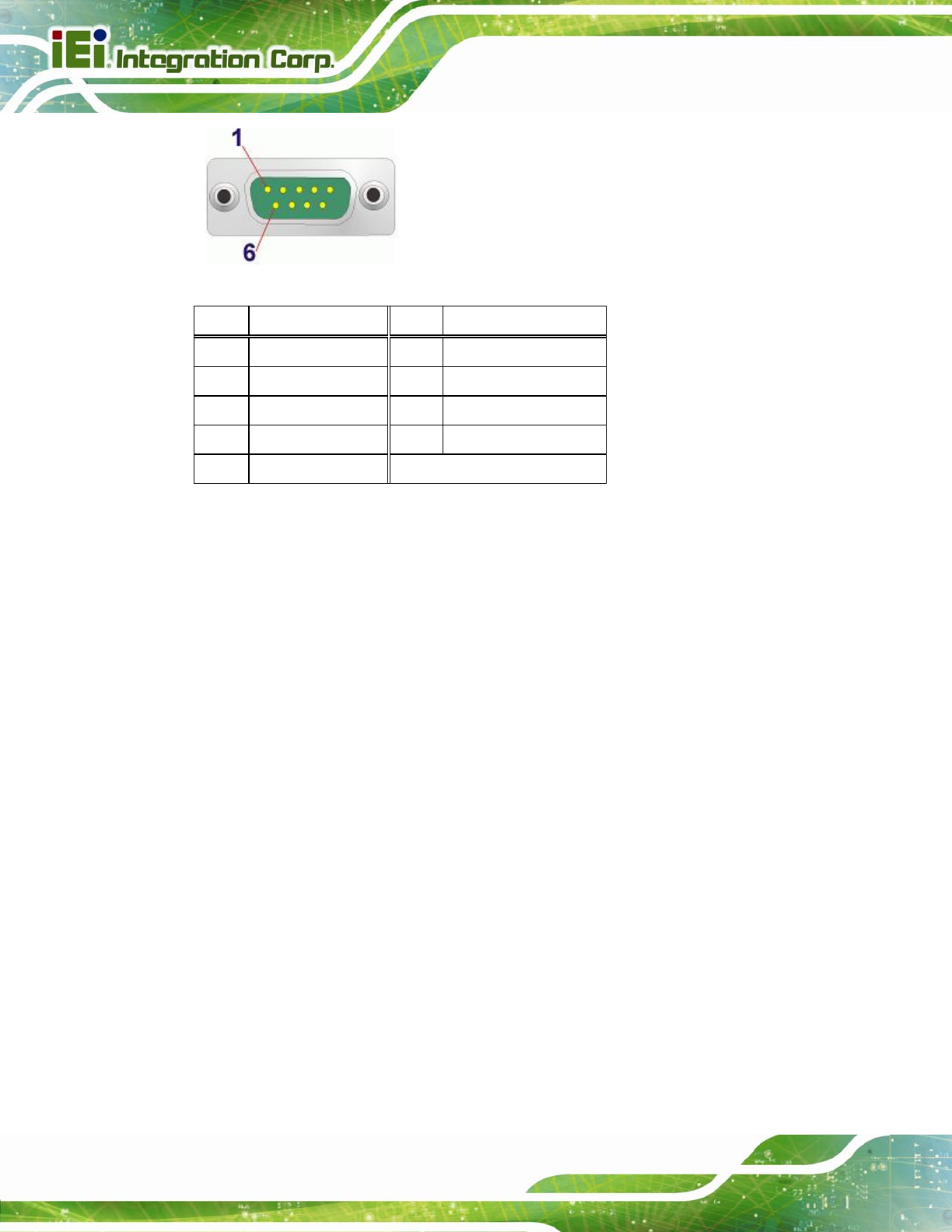
Follow the steps below to connect a serial device to the DB-9 connector of the
AFL2-12A-D525 panel PC.
Step 1: Locate the DB-9 connector. The location of the DB-9 connector is shown in
Chapter 2.
Step 2: Insert the serial connector. Insert the DB-9 connector of a serial device into
the DB-9 connector on the bottom panel. See
Figure 4-20.