
Manual
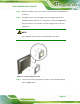
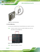

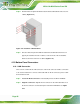


Table Of Contents
- 1 Introduction
- 2 Detailed Specifications
- 3 Unpacking
- 4 Installation
- 5 System Maintenance
- 6 AMI BIOS Setup
- 7 Software Drivers
- A Safety Precautions
- B BIOS Configuration Options
- C One Key Recovery
- D Watchdog Timer
- E Hazardous Materials Disclosure
AFL2-12A-D525 Series Panel PC
Page 57
Figure 4-18: LAN Connection
Step 3: Insert the LAN cable RJ-45 connector. Once aligned, gently insert the LAN
cable RJ-45 connector into the onboard RJ-45 connector. Step 0:
4.10.2 Serial Device Connection
The AFL2-12A-D525 has one male DB-9 port connector and one RJ-45 serial port
connector on the I/O panel for serial device connection.
4.10.2.1 DB-9 Serial Port Connection
CN Label: DB-9
CN Type:
9-pin connector
CN Location:
See
Figure 4-19
CN Pinouts:
See
Table 4-1
A DB-9 serial port device can be connected to the DB-9 serial port on the bottom panel.
The pinouts of the DB-9 serial port are shown below.