
Manual
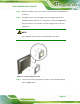
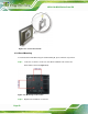
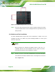

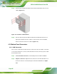


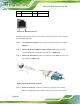
Table Of Contents
- 1 Introduction
- 2 Detailed Specifications
- 3 Unpacking
- 4 Installation
- 5 System Maintenance
- 6 AMI BIOS Setup
- 7 Software Drivers
- A Safety Precautions
- B BIOS Configuration Options
- C One Key Recovery
- D Watchdog Timer
- E Hazardous Materials Disclosure
AFL2-12A-D525 Series Panel PC
Page 56
Step 4: Slide the flat bezel panel PC with the attached rack/cabinet bracket into a rack or
cabinet (
Figure 4-17).
Figure 4-17: Install into a Rack/Cabinet
Step 5: Once the flat bezel panel PC with the attached rack/cabinet bracket has been
properly inserted into the rack or cabinet, secure the front of the rack/cabinet
bracket to the front of the rack or cabinet (
Figure 4-17).Step 0:
4.10 Bottom Panel Connectors
4.10.1 LAN Connection
There are two external RJ-45 LAN connectors. The RJ-45 connector enables connection
to an external network. To connect a LAN cable with an RJ-45 connector, please follow
the instructions below.
Step 1: Locate the RJ-45 connectors on the bottom panel of the AFL2-12A-D525.
Step 2: Align the connectors. Align the RJ-45 connector on the LAN cable with one of
the RJ-45 connectors on the bottom panel of the AFL2-12A-D525. See
Figure
4-18.