
Manual
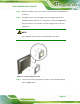
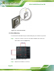
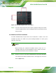

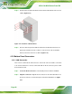


Table Of Contents
- 1 Introduction
- 2 Detailed Specifications
- 3 Unpacking
- 4 Installation
- 5 System Maintenance
- 6 AMI BIOS Setup
- 7 Software Drivers
- A Safety Precautions
- B BIOS Configuration Options
- C One Key Recovery
- D Watchdog Timer
- E Hazardous Materials Disclosure
AFL2-12A-D525 Series Panel PC
Page 54
Figure 4-14: Arm Mounting Retention Screw Holes
Step 4: Secure the flat bezel panel PC to the interface pad by inserting four retention
screws through the bottom of the mounting arm interface pad and into the flat
bezel panel PC. Step 0:
4.9.4 Cabinet and Rack Installation
The AFL2-12A-D525 flat bezel panel PC can be installed into a cabinet or rack. The
installation procedures are similar to the panel mounting installation. To do this, please
follow the steps below:
NOTE:
When purchasing the cabinet/rack installation bracket, make sure it is
compatible with both the AFL2-12A-D525 flat bezel panel PC and the
rack/cabinet into which the AFL2-12A-D525 is installed.
Step 1: Slide the rear chassis of the AFL2-12A-D525 flat bezel panel PC through the
rack/cabinet bracket until the aluminum frame is flush against the front of the
bracket (
Figure 4-15).