
Manual
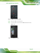
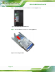
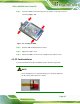
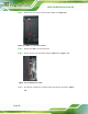

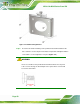
Table Of Contents
- 1 Introduction
- 2 Detailed Specifications
- 3 Unpacking
- 4 Installation
- 5 System Maintenance
- 6 AMI BIOS Setup
- 7 Software Drivers
- A Safety Precautions
- B BIOS Configuration Options
- C One Key Recovery
- D Watchdog Timer
- E Hazardous Materials Disclosure
AFL2-12A-D525 Series Panel PC
Page 50
Figure 4-10: Wall-mounting Bracket
Step 6: Insert the four monitor mounting screws provided in the wall mount kit into the
four screw holes on the real panel of the flat bezel panel PC and tighten until the
screw shank is secured against the rear panel (
Figure 4-11).
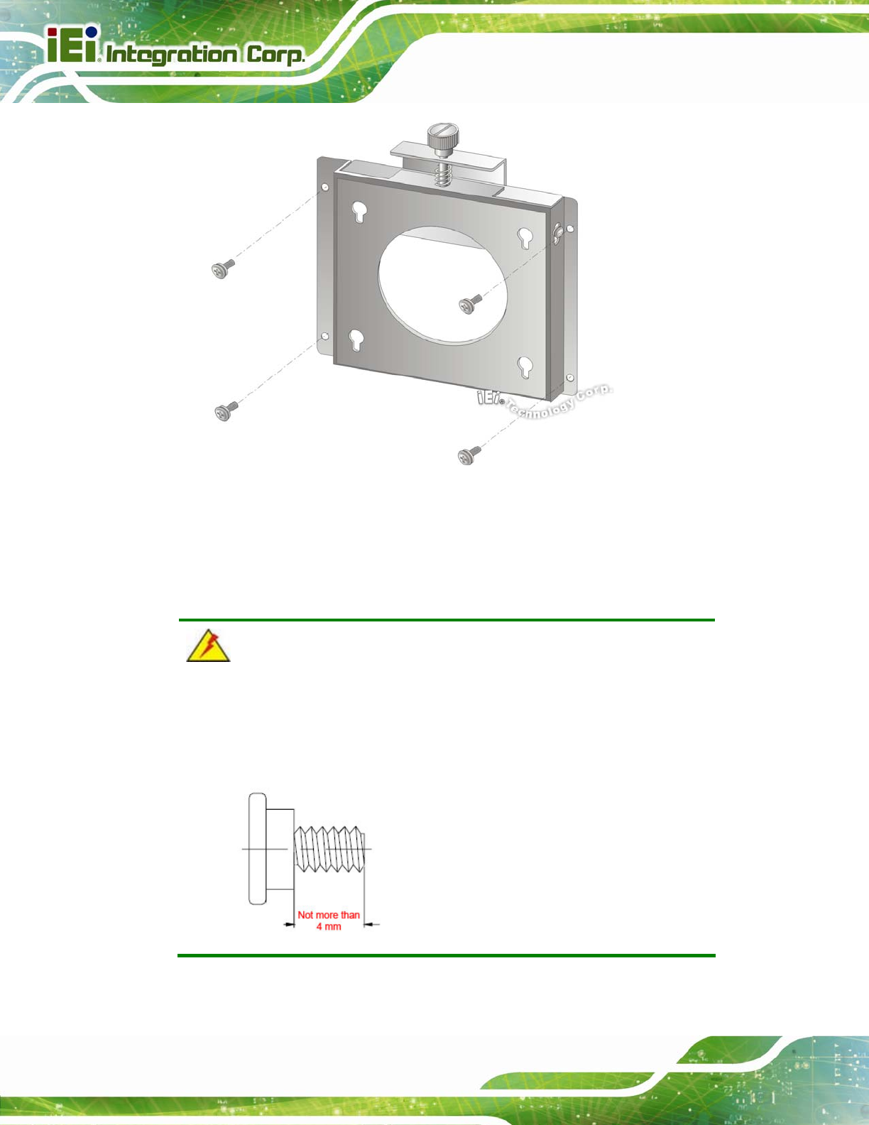
WARNING:
Please use the M4 screws provided in the wall mount kit for the rear panel.
If the screw is missing, the thread depth of the replacement screw should
be not more than 4 mm.