
Manual
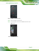
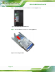
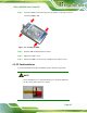
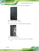
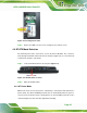

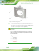
Table Of Contents
- 1 Introduction
- 2 Detailed Specifications
- 3 Unpacking
- 4 Installation
- 5 System Maintenance
- 6 AMI BIOS Setup
- 7 Software Drivers
- A Safety Precautions
- B BIOS Configuration Options
- C One Key Recovery
- D Watchdog Timer
- E Hazardous Materials Disclosure
AFL2-12A-D525 Series Panel PC
Page 47
Figure 4-8: Inserting the CF Card
Step 5: Replace the HDD cover and secure it using two (2) retention screws. Step 0:
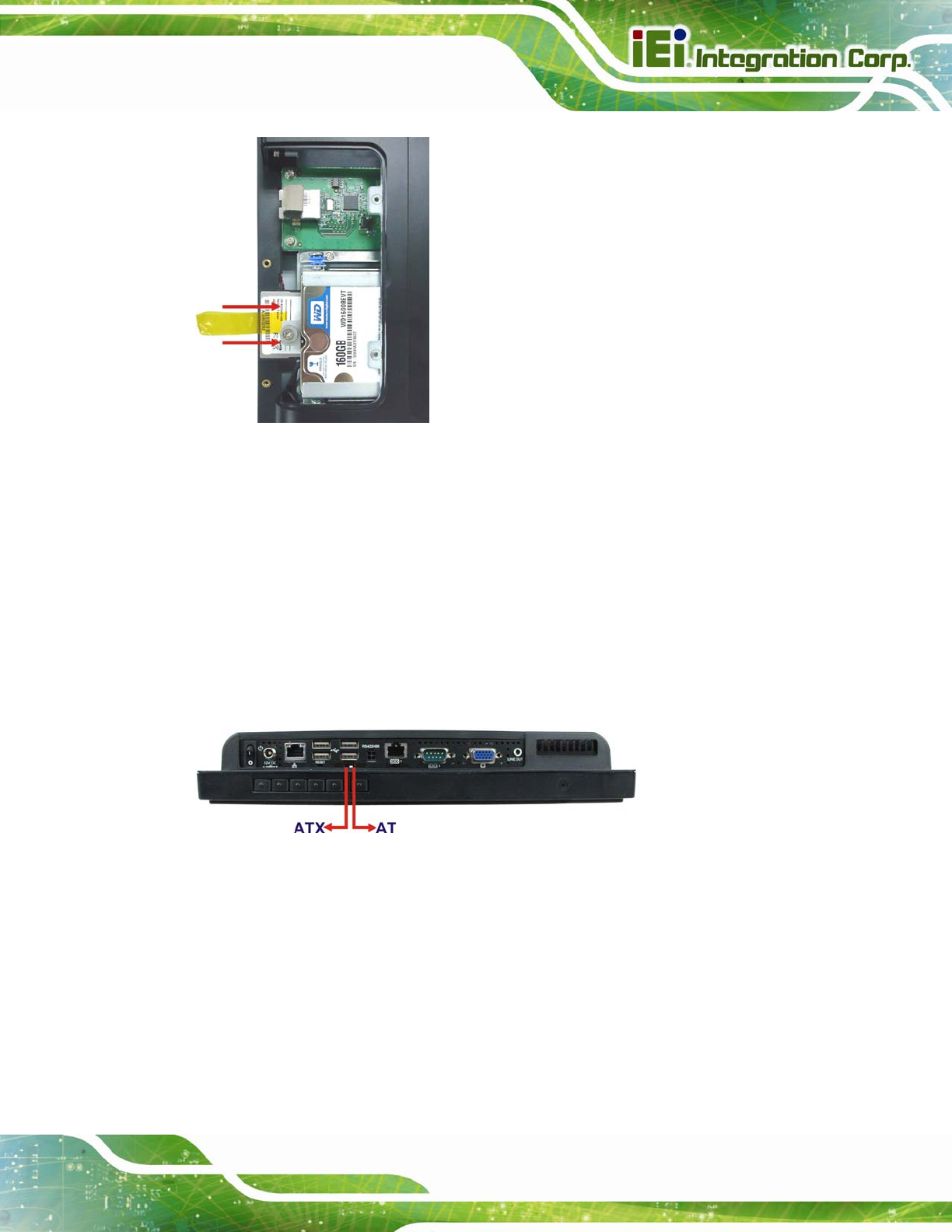
4.6 AT/ATX Mode Selection
AT and ATX power modes can both be used on the AFL2-12A-D525. The selection is
made through an AT/ATX switch located on the I/O panel (
Figure 4-9). To select AT mode
or ATX mode, follow the steps below.
Step 1: Locate the AT/ATX switch on the I/O panel (
Figure 4-9).
Figure 4-9: AT/ATX Switch Location
Step 2: Adjust the AT/ATX switch. Step 0:
4.6.1 AT Power Mode
With the AT mode selected, the power is controlled by a central power unit rather than a
power switch. The AFL2-12A-D525 panel PC turns on automatically when the power is
connected. The AT mode benefits a production line to control multiple panel PCs from a
central management center and other applications including: