
Manual
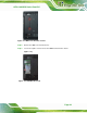
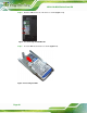
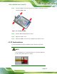
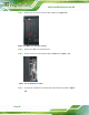
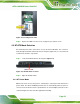

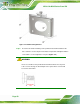
Table Of Contents
- 1 Introduction
- 2 Detailed Specifications
- 3 Unpacking
- 4 Installation
- 5 System Maintenance
- 6 AMI BIOS Setup
- 7 Software Drivers
- A Safety Precautions
- B BIOS Configuration Options
- C One Key Recovery
- D Watchdog Timer
- E Hazardous Materials Disclosure

AFL2-12A-D525 Series Panel PC
Page 46
Step 1: Remove two (2) retention screws from the HDD cover (Figure 4-6).
Figure 4-6: HDD Cover Retention Screws
Step 2: Remove the HDD cover from the device.
Step 3: The CF card slot is located underneath the HDD bracket. (
Figureٛ 4-7).
Figure
ٛ 4-7: CF Card Slot Location
Step 4: Insert the CF card into the slot until it cannot be pushed in any further. (
Figure
4-8).