
Manual

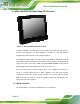
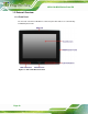
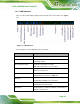
Table Of Contents
- 1 Introduction
- 2 Detailed Specifications
- 3 Unpacking
- 4 Installation
- 5 System Maintenance
- 6 AMI BIOS Setup
- 7 Software Drivers
- A Safety Precautions
- B BIOS Configuration Options
- C One Key Recovery
- D Watchdog Timer
- E Hazardous Materials Disclosure
AFL2-12A-D525 Series Panel PC
Page 19
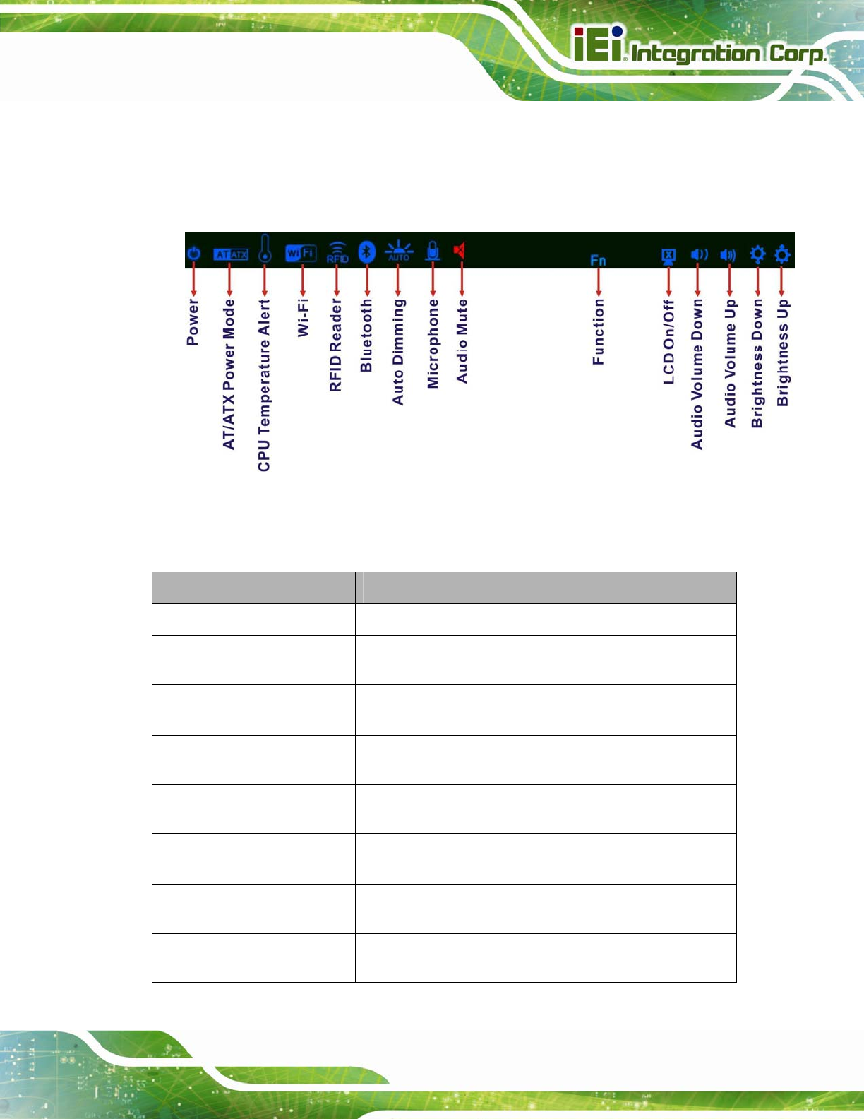
1.2.1.1 LED Indicators
There are fifteen LED indicator lights located along the front of the LCD screen (Figure
1-3).
Figure 1-3: LED Indicators
The descriptions of each LED indicator are listed below.
LED Indicator Description
Power
Shows power on/off status.
AT/ATX Mode
Shows the power mode status. Controlled by the AT/ATX
power mode switch.
CPU Temperature Alert
BLUE: CPU temperature is normal.
RED: CPU temperature is at or over 95ºC.
Wi-Fi
The Wi-Fi module is enabled or disabled. Controlled by the
BIOS. See Section
6.5.2
RFID
The optional RFID reader is enabled or disabled.
Controlled by the hot keys. See
Table 1-3
Bluetooth
The Bluetooth module is enabled or disabled.
Controlled by the BIOS. See Section
6.5.2
Auto-Dimming
The auto-dimming function is enabled or disabled.
Controlled by the remote control
Microphone
The microphone is enabled or disabled. Controlled by the
BIOS. See Section
6.5.2