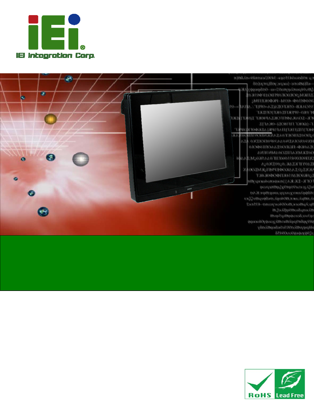
AFL2-12A-D525 Series Panel PC MODEL: AFL2-12A-D525 Fanless Flat Bezel Panel PC with 1.8 GHz Intel® Atom™ Processor TFT LCD, Wi-Fi, Touch Screen, RFID Reader, Dual GbE LAN RS-232/422/485, Camera, RoHS User Manual Page I Rev. 1.
AFL2-12A-D525 Series Panel PC Revision Date Version Changes 25 July, 2013 1.02 Added information of the CPU temperature alert LED in Section 1.2.1.1 9 December, 2011 1.01 Added Warning page IV Revised Section 1.4 System Specifications Revised Section 3.1.1 Packing List Added Section 4.9.2 Stand Mounting Updated Section 4.10.2.1 DB-9 Serial Port Connection Updated Section 4.10.2.2 RJ-45 Serial Port Connection Updated Section 4.10.3 RS-422/485 Serial Port Added Section A.1.
AFL2-12A-D525 Series Panel PC Copyright COPYRIGHT NOTICE The information in this document is subject to change without prior notice in order to improve reliability, design and function and does not represent a commitment on the part of the manufacturer. In no event will the manufacturer be liable for direct, indirect, special, incidental, or consequential damages arising out of the use or inability to use the product or documentation, even if advised of the possibility of such damages.
AFL2-12A-D525 Series Panel PC WARNING: This equipment has been tested and found to comply with the limits for a Class A digital device, pursuant to Part 15 of the FCC Rules. These limits are designed to provide reasonable protection against harmful interference in a residential installation. This equipment generates, uses and can radiate radio frequency energy and, if not installed and used in accordance with the instructions, may cause harmful interference to radio communications.
AFL2-12A-D525 Series Panel PC Table of Contents 1 INTRODUCTION........................................................................................................ 15 1.1 AFL2-12A-D525 FLAT BEZEL PANEL PC OVERVIEW .............................................. 16 1.1.1 Model Variations .............................................................................................. 16 1.1.2 Features ...........................................................................................................
AFL2-12A-D525 Series Panel PC 2.7 SYSTEM POWER ....................................................................................................... 33 2.7.1 Power Mode ..................................................................................................... 33 2.7.1.1 ATX Power Mode (Default)...................................................................... 33 2.7.1.2 AT Power Mode ........................................................................................ 33 2.7.
AFL2-12A-D525 Series Panel PC 5.2 ANTI-STATIC PRECAUTIONS ...................................................................................... 65 5.3 TURN OFF THE POWER .............................................................................................. 66 5.4 OPENING THE SYSTEM.............................................................................................. 66 5.4.1 Removing the Back Cover................................................................................ 66 5.4.
AFL2-12A-D525 Series Panel PC 7 SOFTWARE DRIVERS ............................................................................................ 104 7.1 AVAILABLE SOFTWARE DRIVERS ............................................................................ 105 7.2 STARTING THE DRIVER PROGRAM .......................................................................... 105 7.3 CHIPSET DRIVER INSTALLATION ............................................................................. 105 7.
AFL2-12A-D525 Series Panel PC C.4 SETUP PROCEDURE FOR LINUX .............................................................................. 154 C.5 RECOVERY TOOL FUNCTIONS ................................................................................ 158 C.5.1 Factory Restore ............................................................................................. 159 C.5.2 Backup System............................................................................................... 160 C.5.
AFL2-12A-D525 Series Panel PC List of Figures Figure 1-1: AFL2-12A-D525 Flat Bezel Panel PC .......................................................................16 Figure 1-2: AFL2-12A-D525 Front View ......................................................................................18 Figure 1-3: LED Indicators...........................................................................................................19 Figure 1-4: Function Keys .........................................................
AFL2-12A-D525 Series Panel PC Figure 4-17: Install into a Rack/Cabinet .....................................................................................56 Figure 4-18: LAN Connection ......................................................................................................57 Figure 4-19: DB-9 Connector.......................................................................................................58 Figure 4-20: DB-9 Serial Port Connector................................................
AFL2-12A-D525 Series Panel PC Figure 7-19: Touch Screen Driver Choose Install Location .................................................. 117 Figure 7-20: Touch Screen Driver Installation Screen........................................................... 118 Figure 7-21: Touch Screen Driver Update Complete ............................................................. 118 Figure 7-22: PenMount Monitor Icon .......................................................................................
AFL2-12A-D525 Series Panel PC Figure C-25: Building the Auto Recovery Partition................................................................ 152 Figure C-26: Factory Default Image Confirmation ................................................................. 152 Figure C-27: Image Creation Complete ................................................................................... 153 Figure C-28: Press any key to continue ..................................................................................
AFL2-12A-D525 Series Panel PC List of Tables Table 1-1: AFL2-12A-D525 Model Variations .............................................................................17 Table 1-2: LED Indicators ............................................................................................................20 Table 1-3: Function Key Descriptions ........................................................................................21 Table 1-4: System Specifications...............................................
AFL2-12A-D525 Series Panel PC Chapter 1 1 Introduction Page 15
AFL2-12A-D525 Series Panel PC 1.1 AFL2-12A-D525 Flat Bezel Panel PC Overview Figure 1-1: AFL2-12A-D525 Flat Bezel Panel PC The AFL2-12A-D525 is an Intel® Atom™ powered flat bezel panel PC with a rich variety of functions and peripherals. The AFL2-12A-D525 is designed for easy and simplified integration into kiosk and point-of-sales (POS) applications.
AFL2-12A-D525 Series Panel PC Model No. Touch Screen Type Optional Features AFL2-12A-D525/PC-EM/1G-R10 Projective capacitive EM card reader AFL2-12A-D525/PC-MF/1G-R10 Projective capacitive MIFARE card reader AFL2-12A-D525/PC/1G-R10 Projective capacitive N/A AFL2-12A-D525/R-EM/1G-R10 5-Wire Resistive EM card reader AFL2-12A-D525/R-MF/1G-R10 5-Wire Resistive MIFARE card reader AFL2-12A-D525/R/1G-R10 5-Wire Resistive N/A Table 1-1: AFL2-12A-D525 Model Variations 1.1.
AFL2-12A-D525 Series Panel PC 1.2 External Overview 1.2.1 Front Panel The front side of the AFL2-12A-D525 is a flat bezel panel TFT LCD screen surrounded by an ABS/PC plastic frame.
AFL2-12A-D525 Series Panel PC 1.2.1.1 LED Indicators There are fifteen LED indicator lights located along the front of the LCD screen (Figure 1-3). Figure 1-3: LED Indicators The descriptions of each LED indicator are listed below. LED Indicator Description Power Shows power on/off status. AT/ATX Mode Shows the power mode status. Controlled by the AT/ATX power mode switch. CPU Temperature Alert BLUE: CPU temperature is normal. RED: CPU temperature is at or over 95ºC.
AFL2-12A-D525 Series Panel PC LED Indicator Description Audio Mute Lights on when the audio is turned off. Controlled by the hot keys. See Table 1-3 Function Shows the status of the function key below the LED indicator. Blinks when the corresponding button is pushed. LCD On/Off Audio Volume Down Audio Volume Up Brightness Down Brightness Up Table 1-2: LED Indicators NOTE: When the CPU temperature is at or over 95ºC, the CPU temperature alert LED shows in red.
AFL2-12A-D525 Series Panel PC The Function Keys are described in Table 1-3: Key Combination Function Key Description Fn + LCD On/Off RFID Enable/Disable Fn + Audio Volume Down Audio Mute Fn + Audio Volume Up Camera Enable/Disable Fn + Brightness Down Mini USB / MicroSD Enable/Disable Fn + Brightness Up Power On/Off Note: To power on the system, hold down the Fn + Brightness buttons for 3 seconds. To power down the system, hold down the FN + Brightness buttons for six seconds.
AFL2-12A-D525 Series Panel PC 1.2.3 I/O Interface Panel The I/O interface panel located on the bottom of the AFL2-12A-D525 has the following features: Page 22 1 x Audio jack 1 x 9V ~ 36V DC-IN power jack 1 x VGA port 1 x RS-232 DB-9 connector 1 x RS-422/485 connector 2 x GbE connectors 4 x USB 2.
AFL2-12A-D525 Series Panel PC The external I/O interface connector panel is shown in Figure 1-6. Figure 1-6: AFL2-12A-D525 I/O Interface Panel 1.2.4 Top Panel and Side Panels The top panel and side panels of AFL2-12A-D525 provide access to slots that support the panel mount and rack mount (Figure 1-7).
AFL2-12A-D525 Series Panel PC Figure 1-8: Side Panel Views 1.3 Internal Overview The AFL2-12A-D525 has the following components installed internally: 1 x Motherboard 1 x 1.0 GB 800 MHz DDR3 SO-DIMM 1.4 System Specifications The technical specifications for the AFL2-12A-D525 systems are listed in Table 1-4. Specification AFL2-12A-D525 LCD Size 12.1” Max.
AFL2-12A-D525 Series Panel PC Contrast Ratio 700:1 LCD Color 16.2M Pixel Pitch (H x V) (mm) 0.240 (H) x 0.240 (V) Viewing Angle (H-V) 176 / 176 Backlight MTBF (hr) 50,000 Touch Screen 5-Wire resistive type touchscreen (select models only) Projected capacitive type touchscreen (select models only) SBC Model AFL2MB2-PV-D525 CPU Intel® Atom™ D525 1.8 GHz Dual Core Processor Chipset Intel® ICH8M Ethernet Realtek RTL8111E PCIe GbE controller supports ASF2.
AFL2-12A-D525 Series Panel PC Power Adapter 65W Input: 100V AC ~ 240V AC @ 50 / 60 Hz Output: 19V DC Power Requirement 9V ~ 36V DC Power Consumption 42W LED Functions Power / RFID / MIC / Auto-dimming / Wi-Fi / RFID device / AT/ATX mode / Camera / Bluetooth / USB port / CPU temperature alert I/O Ports and Switches 1 x RS-232 (DB-9 connector) 1 x RS-232 (RJ-45 connector) 1 x RS-422/485 (4-pin box header) 2 x GbE LAN (RJ-45 connector) 4 x USB 2.0 connector 1 x Mini USB 2.
AFL2-12A-D525 Series Panel PC Chapter 2 2 Detailed Specifications Page 27
AFL2-12A-D525 Series Panel PC 2.1 Dimensions The AFL2-12A-D525 dimensions are shown below. Width: 310.0 mm Height: 265.0 mm Depth: 52.
AFL2-12A-D525 Series Panel PC Figure 2-2: AFL2-12A-D525 Dimensions (mm) cont. 2.2 Intel® Atom™ Processor An Intel® Atom™ D525 processor is installed in the system. The D525 CPU is a 1.8 GHz dual core processor with Direct Media Interface (DMI) speed of 2.5 GT/s. The CPU also features a 1.0 MB L2 cache. 2.3 Motherboard Components The following sections describe some of the features on the motherboard.
AFL2-12A-D525 Series Panel PC 2.3.1 Memory Support 2.3.1.1 Installed Memory One 204-pin 1.0 GB 800 MHz DDR3 SO-DIMM is installed in the AFL2-12A-D525 and controlled by the Intel® Atom™ D525 CPU installed on the internal motherboard. 2.3.2 Storage Capacity The AFL2-12A-D525 comes equipped with a CompactFlash® Type II (CF Type II) memory disk slot. The AFL2-12A-D525 also supports a 2.5” SATA HDD drive bay which can be easily accessed by removing two screws on the HDD cover. 2.
AFL2-12A-D525 Series Panel PC 2.4.2 LAN Connectivity The AFL2-12A-D525 has one RJ-45 LAN connector on the bottom panel. Figure 2-4: RJ-45 Ethernet Connectors The PCIe LAN from the Intel® ICH8M chipset of the AFL2-12A-D525 is interfaced to the Realtek RTL8111E PCIe gigabit Ethernet (GbE) controllers. The RTL8111E controller is connected directly to the RJ-45 connector on the bottom panel and provides external GbE connectivity. 2.4.3 External USB Connectors There are four USB 2.
AFL2-12A-D525 Series Panel PC Figure 2-6: LCD Screen 2.5.2 Touch-Screen Module A controller for the touch screen is installed on the motherboard. The sensitive touch screen is accurate, reliable and durable. 2.6 Audio 2.6.1 Audio Codec Controller The integrated HD Audio compliant audio controller on the Intel® ICH8-M Southbridge is integrated to a Realtek ALC888 audio codec. The Realtek ALC888 is connected to an external audio jack, which is then connected to compliant audio devices.
AFL2-12A-D525 Series Panel PC 2.6.2 Stereo Speakers Two internal 1.5 W stereo speakers on the sides of the AFL2-12A-D525 are interfaced to the system. 2.7 System Power 2.7.1 Power Mode The system can be run in the AT power mode or the ATX power mode. Both these power modes are described below. 2.7.1.1 ATX Power Mode (Default) With the ATX mode selected, the AFL2-12A-D525 panel PC goes in a standby mode when it is turned off.
AFL2-12A-D525 Series Panel PC 2.7.2 Power Adapter The system is shipped with a 100 V to 240 V AC power adapter that has a maximum power output of 65 W. The power adapter has a 19 V DC output connector.
AFL2-12A-D525 Series Panel PC Chapter 3 3 Unpacking Page 35
AFL2-12A-D525 Series Panel PC 3.1 Unpacking To unpack the flat bezel panel PC, follow the steps below: WARNING! The front side LCD screen has a protective plastic cover stuck to the screen. Only remove the plastic cover after the flat bezel panel PC has been properly installed. This ensures the screen is protected during the installation process. Step 1: Use box cutters, a knife or a sharp pair of scissors that seals the top side of the external (second) box. Step 2: Open the external (second) box.
AFL2-12A-D525 Series Panel PC 1 Power adapter (P/N: 63040-010065-010-RS) 1 Power cord (P/N: 32702-000401-100-RS) 1 Power Transfer Cord (P/N:32000-089400-RS) 4 M3 Screws Pack (P/N: 44013-030041-RS) 4 M4 Screws Pack (P/N: 44403-040061-RS) 1 Touch Pen (P/N: 43125-0002C0-00-RS) 1 RJ-45 to DB-9 COM Port Cable (P/N: 32005-000200-200-RS) 1 RS-422 cable (P/N: 32205-002400-100-RS) 1 IR Remote Control (P/N: 7Z000-8T00320ICP05G-RS) 1 User manual CD and driver CD 1 One Key Recovery CD (P/N: 7B000-0
AFL2-12A-D525 Series Panel PC Optional Wall mounting kit (P/N: AFLWK-19/AFLWK-19B) Arm (P/N: ARM-11-RS) Stand (P/N: STAND-A12) V-Stand (P/N: VSTAND-A12) Hybrid Card Reader (P/N: AFL2P-12AMSI-U-R10) Magnetic Stripe Reader (P/N: AFL2P-12AMSR-U-R10) Rack Mounting Kit (P/N: AFL2RK-12) OS: Win CE 6.
AFL2-12A-D525 Series Panel PC OS: Win XPE (2GB CF Card) (P/N: AFL2CF-12-D525-XPE-2G-R10) OS: Win XPE (4GB CF Card) (P/N: AFL2CF-12-D525-XPE-4G-R10) OS: Linux (2GB CF Card) (P/N: AFL2CF-12A-D525-LNX-R10) OS: Win 7 Embedded (4GB CF Card) (P/N: AFL2CF-12-D525-WES7P-4G-R10 AFL2CF-12-D525-WES7E-4G-R10) If any of these items are missing or damaged, contact the distributor or sales representative immediately.
AFL2-12A-D525 Series Panel PC Chapter 4 4 Page 40 Installation
AFL2-12A-D525 Series Panel PC 4.1 Anti-static Precautions WARNING: Failure to take ESD precautions during the maintenance of the AFL2-12A-D525 may result in permanent damage to the AFL2-12A-D525 and severe injury to the user. Electrostatic discharge (ESD) can cause serious damage to electronic components, including the AFL2-12A-D525. Dry climates are especially susceptible to ESD.
AFL2-12A-D525 Series Panel PC Anti-static Discharge: If a user open the rear panel of the flat bezel panel PC, to configure the jumpers or plug in added peripheral devices, ground themselves first and wear and anti-static wristband. 4.3 Installation and Configuration Steps The following installation steps must be followed.
AFL2-12A-D525 Series Panel PC Figure 4-1: HDD Cover Retention Screws Step 2: Remove the HDD cover from the device. Step 3: Loosen the captive screw to release the HDD bracket from the chassis (Figureٛ 4-2).
AFL2-12A-D525 Series Panel PC Step 4: Slide the HDD bracket out of the device as shown (Figureٛ 4-3). Figureٛ 4-3: Removing the HDD Bracket Step 5: Insert an HDD into the bracket as shown (Figure 4-4).
AFL2-12A-D525 Series Panel PC Step 6: Secure the HDD to the bracket using four (4) retention screws (two screws on each side) (Figureٛ 4-5). Figureٛ 4-5: Securing the HDD Step 7: Slide the HDD module back into the device. Step 8: Tighten the captive screw. Step 9: Replace the HDD cover and secure it using two (2) retention screws. Step 0: 4.
AFL2-12A-D525 Series Panel PC Step 1: Remove two (2) retention screws from the HDD cover (Figure 4-6). Figure 4-6: HDD Cover Retention Screws Step 2: Remove the HDD cover from the device. Step 3: The CF card slot is located underneath the HDD bracket. (Figureٛ 4-7). Figureٛ 4-7: CF Card Slot Location Step 4: Insert the CF card into the slot until it cannot be pushed in any further. (Figure 4-8).
AFL2-12A-D525 Series Panel PC Figure 4-8: Inserting the CF Card Step 5: Replace the HDD cover and secure it using two (2) retention screws. Step 0: 4.6 AT/ATX Mode Selection AT and ATX power modes can both be used on the AFL2-12A-D525. The selection is made through an AT/ATX switch located on the I/O panel (Figure 4-9). To select AT mode or ATX mode, follow the steps below. Step 1: Locate the AT/ATX switch on the I/O panel (Figure 4-9). Figure 4-9: AT/ATX Switch Location Step 2: Adjust the AT/ATX switch.
AFL2-12A-D525 Series Panel PC ATM Self-service kiosk Plant environment monitoring system Factory automation platform Manufacturing shop flow 4.6.2 ATX Power Mode With the ATX mode selected, the AFL2-12A-D525 panel PC goes in a standby mode when it is turned off. The panel PC can be easily turned on via network or a power switch in standby mode.
AFL2-12A-D525 Series Panel PC 4.9 Mounting the System WARNING! When mounting the flat bezel panel PC onto an arm, onto the wall or onto a panel, it is better to have more than one person to help with the installation to make sure the panel PC does not fall down and get damaged. The four methods of mounting the AFL2-12A-D525 are listed below. Wall mounting Stand mounting Arm mounting Rack mounting The four mounting methods are described below. 4.9.
AFL2-12A-D525 Series Panel PC Figure 4-10: Wall-mounting Bracket Step 6: Insert the four monitor mounting screws provided in the wall mount kit into the four screw holes on the real panel of the flat bezel panel PC and tighten until the screw shank is secured against the rear panel (Figure 4-11). WARNING: Please use the M4 screws provided in the wall mount kit for the rear panel. If the screw is missing, the thread depth of the replacement screw should be not more than 4 mm.
AFL2-12A-D525 Series Panel PC Step 7: Align the mounting screws on the monitor rear panel with the mounting holes on the bracket. Step 8: Carefully insert the screws through the holes and gently pull the monitor downwards until the monitor rests securely in the slotted holes (Figure 4-11). Ensure that all four of the mounting screws fit snuggly into their respective slotted holes. NOTE: In the diagram below the bracket is already installed on the wall.
AFL2-12A-D525 Series Panel PC Figure 4-12: Secure the Panel PC 4.9.2 Stand Mounting To mount the AFL2-12A-D525 using the stand mounting kit, please follow the steps below. Step 1: Locate the screw holes on the rear of the AFL2-12A-D525. This is where the bracket will be attached. (Figure 4-13) Figure 4-13: Mounting screw location Step 2: Align the bracket with the screw holes.
AFL2-12A-D525 Series Panel PC Step 3: To secure the bracket to the AFL2-12A-D525, insert the retention screws into the screw holes and tighten them. Step 0: 4.9.3 Arm Mounting The AFL2-12A-D525 is VESA (Video Electronics Standards Association) compliant and can be mounted on an arm with a 100mm interface pad. To mount the AFL2-12A-D525 on an arm, please follow the steps below. Step 1: The arm is a separately purchased item. Please correctly mount the arm onto the surface it uses as a base.
AFL2-12A-D525 Series Panel PC Figure 4-14: Arm Mounting Retention Screw Holes Step 4: Secure the flat bezel panel PC to the interface pad by inserting four retention screws through the bottom of the mounting arm interface pad and into the flat bezel panel PC. Step 0: 4.9.4 Cabinet and Rack Installation The AFL2-12A-D525 flat bezel panel PC can be installed into a cabinet or rack. The installation procedures are similar to the panel mounting installation.
AFL2-12A-D525 Series Panel PC Figure 4-15: The Rack/Cabinet Bracket Step 2: Insert the rack mounting clamps into the pre-formed holes along the edges of the flat bezel panel PC, behind the ABS/PC plastic frame. There are a total of 6 rack mounting clamps. Step 3: Tighten the screws that pass through the rack mounting clamps until the plastic caps at the front of all the screws are firmly secured to the bracket (Figure 4-16).
AFL2-12A-D525 Series Panel PC Step 4: Slide the flat bezel panel PC with the attached rack/cabinet bracket into a rack or cabinet (Figure 4-17). Figure 4-17: Install into a Rack/Cabinet Step 5: Once the flat bezel panel PC with the attached rack/cabinet bracket has been properly inserted into the rack or cabinet, secure the front of the rack/cabinet bracket to the front of the rack or cabinet (Figure 4-17).Step 0: 4.10 Bottom Panel Connectors 4.10.
AFL2-12A-D525 Series Panel PC Figure 4-18: LAN Connection Step 3: Insert the LAN cable RJ-45 connector. Once aligned, gently insert the LAN cable RJ-45 connector into the onboard RJ-45 connector. Step 0: 4.10.2 Serial Device Connection The AFL2-12A-D525 has one male DB-9 port connector and one RJ-45 serial port connector on the I/O panel for serial device connection. 4.10.2.
AFL2-12A-D525 Series Panel PC Figure 4-19: DB-9 Connector Pin Description Pin Description 1 DCD1 2 RX1 3 TX1 4 DTR1 5 GND 6 DSR1 7 RTS1 8 CTS1 9 RI1 Table 4-1: DB-9 Connector Pinouts Follow the steps below to connect a serial device to the DB-9 connector of the AFL2-12A-D525 panel PC. Step 1: Locate the DB-9 connector. The location of the DB-9 connector is shown in Chapter 2. Step 2: Insert the serial connector.
AFL2-12A-D525 Series Panel PC Figure 4-20: DB-9 Serial Port Connector Step 3: Secure the connector. Secure the serial device connector to the external interface by tightening the two retention screws on either side of the connector. 4.10.2.2 RJ-45 Serial Port Connection CN Label: COM3 CN Type: RJ-45 CN Location: See Figure 4-21 CN Pinouts: See Table 4-2 A 10/100/1000 Mb/s connection can be made to a Local Area Network.
AFL2-12A-D525 Series Panel PC Pin Description Pin Description 4 RTS3 8 RI3 Table 4-2: Ethernet Connector Pinouts Figure 4-21: Ethernet Connector Follow the steps below to connect a serial device to the RJ-45 serial port connector of the AFL2-12A-D525 panel PC. Step 1: Locate the RJ-45 serial port. The location of the RJ-45 serial port is shown in Chapter 2. Step 2: Connect the RJ-45 to COM port cable to the panel PC. Insert the RJ-45 connector end of cable into the RJ-45 serial port.
AFL2-12A-D525 Series Panel PC 4.10.3 RS-422/485 Serial Port CN Label: RS 422/485 CN Type: 4-pin connector CN Location: See Figure 4-23 CN Pinouts: See Table 4-3 and Figure 4-24 A RS-422/485 serial port device can be connected to the RS-422/485 serial port on the bottom panel. The pinouts of the RS-422/485 serial port are shown below.
AFL2-12A-D525 Series Panel PC Step 3: Insert the serial connector. Insert the DB-9 connector of a serial device into the DB-9 connector on the RS-422/485 cable. Step 4: Secure the connector. Secure the serial device connector to the external interface by tightening the two retention screws on either side of the connector. Step 5: The DB-9 connector pinouts are listed below.
AFL2-12A-D525 Series Panel PC Figure 4-26: USB Device Connection Step 3: Insert the device connector. Once aligned, gently insert the USB device connector into the onboard connector.
AFL2-12A-D525 Series Panel PC Chapter 5 5 Page 64 System Maintenance
AFL2-12A-D525 Series Panel PC 5.1 System Maintenance Introduction If the components of the AFL2-12A-D525 fail they must be replaced. Components that can be replaced include: SO-DIMM module WLAN Module Please contact the system reseller or vendor to purchase the replacement parts. Back cover removal instructions for the AFL2-12A-D525 are described below. 5.
AFL2-12A-D525 Series Panel PC 5.3 Turn off the Power WARNING: Failing to turn off the system before opening it can cause permanent damage to the system and serious or fatal injury to the user. Before any maintenance procedures are carried out on the system, make sure the system is turned off. To power off the system, follow the steps below: Step 1: Locate the Function and Brightness Up function keys. See Section 1.2.1.1.
AFL2-12A-D525 Series Panel PC Step 3: Remove a total of nine (9) retention screws from the back cover (Figure 5-1). Figure 5-1: Back Cover Retention Screws Step 4: Carefully separate the back cover from the chassis and lift the cover clear of the device Step 0: 5.4.2 Removing the Internal Aluminum Cover To remove the internal aluminum cover, follow the steps below. Step 1: Remove the six (6) retention screws securing the internal aluminum cover to the chassis (Figure 5-2).
AFL2-12A-D525 Series Panel PC Figureٛ 5-2: Internal Cover Retention Screws Step 2: Lift the aluminum cover off the AFL2-12A-D525. Step 0: 5.5 Replacing Components 5.5.1 Memory Module Replacement The flat bezel panel PC is preinstalled with a 1.0 GB DDR3 memory module. If the memory module fails, follow the instructions below to replace the memory module. Step 1: Follow all anti-static procedures. See Section 5.2. Step 2: Turn off the power. See Section 5.3. Step 3: Remove the back cover. See Section 5.4.
AFL2-12A-D525 Series Panel PC Step 8: Install the new DDR3 memory module by pushing it into the socket at an angle (Figure 5-3). Step 9: Gently pull the spring retainer clips of the SO-DIMM socket out and push the rear of the DDR memory module down (Figure 5-3). Step 10: Release the spring retainer clips on the SO-DIMM socket. They clip into place and secure the DDR memory module in the socket.
AFL2-12A-D525 Series Panel PC Step 5: Locate the WLAN card. Step 6: Disconnect the main and auxiliary antennas on the WLAN module (Figureٛ 5-4). Figureٛ 5-4: Removing the Antennas Step 7: Push the two spring clips in to release the WLAN card.
AFL2-12A-D525 Series Panel PC Step 8: Grasp the WLAN card by the edges and carefully pull it out of the socket (Figureٛ 5-6). Figureٛ 5-6: Removing the WLAN card Step 9: Install a new WLAN card by inserting the card into the slot at an angle Step 10: Push the WLAN card down until the spring retainer clips lock into place.
AFL2-12A-D525 Series Panel PC Step 11: Connect the main (1) and auxiliary (2) antennas. The main antenna is indicated with a strip of black electrical tape. See Figureٛ 5-7. NOTE: To ensure the WLAN module functions correctly, please make sure the WLAN antennas are attached in the proper configuration. Figureٛ 5-7: Attaching the Antennas Step 12: Replace the internal aluminum cover and secure it to the chassis using six (6) retention screws.
AFL2-12A-D525 Series Panel PC 5.6 Reinstalling the Covers WARNING: Failing to reinstall the covers may result in permanent damage to the system. Please make sure all coverings are properly installed.
AFL2-12A-D525 Series Panel PC Chapter 6 6 AMI BIOS Setup Page 74
AFL2-12A-D525 Series Panel PC 6.1 Introduction A licensed copy of the BIOS is preprogrammed into the ROM BIOS. The BIOS setup program allows users to modify the basic system configuration. This chapter describes how to access the BIOS setup program and the configuration options that may be changed. 6.1.1 Starting Setup The UEFI BIOS is activated when the computer is turned on. The setup program can be activated in one of two ways. 1. Press the F2 key as soon as the system is turned on or 2.
AFL2-12A-D525 Series Panel PC Esc key Main Menu – Quit and do not save changes into CMOS Status Page Setup Menu and Option Page Setup Menu -Exit current page and return to Main Menu F1 key General help, only for Status Page Setup Menu and Option Page Setup Menu F9 key Load optimized defaults F10 key Save changes and Exit BIOS Table 6-1: BIOS Navigation Keys 6.1.
AFL2-12A-D525 Series Panel PC 6.2 Main The Main BIOS menu (BIOS Menu 1) appears when the BIOS Setup program is entered. 6 The Main menu gives an overview of the basic system information. Aptio Setup Utility – Copyright (C) 2010 American Megatrends, Inc. Main Advanced Chipset Boot Security Save & Exit BIOS Information BIOS Vendor Core Version Compliency Project Version Build Date and Time American Megatrends 4.6.4.0 0.20 UEFI 2.0 SC55AR11.ROM 07/20/2011 16:55:39 Set the Date.
AFL2-12A-D525 Series Panel PC Î System Time [xx:xx:xx] Use the System Time option to set the system time. Manually enter the hours, minutes and seconds. 6.3 Advanced Use the Advanced menu (BIOS Menu 2) to configure the CPU and peripheral devices 6 through the following sub-menus: WARNING: Setting the wrong values in the sections below may cause the system to malfunction. Make sure that the settings made are compatible with the hardware.
AFL2-12A-D525 Series Panel PC Aptio Setup Utility – Copyright (C) 2010 American Megatrends, Inc. Main Advanced Chipset Boot Security Save & Exit > > > > > > > > ACPI Settings CPU Configuration IDE Configuration USB Configuration Super IO Configuration H/M Monitor Serial Port Console Redirection iEi Feature System ACPI Parameters. ---------------------- ÅÆ: Select Screen ↑ ↓: Select Item Enter Select +/-: Change Opt.
AFL2-12A-D525 Series Panel PC Î ACPI Sleep State [S1 (CPU Stop Clock)] Use the ACPI Sleep State option to specify the sleep state the system enters when it is not being used. Î S1 (CPU Stop DEFAULT The system enters S1 (POS) sleep state. The system appears off. The CPU is stopped; RAM is Clock) refreshed; the system is running in a low power mode. Î S3 (Suspend The caches are flushed and the CPU is powered to off. Power to the RAM is maintained.
AFL2-12A-D525 Series Panel PC Aptio Setup Utility – Copyright (C) 2010 American Megatrends, Inc. Advanced CPU Configuration Processor Type EMT64 Processor Speed System Bus Speed Ratio Status Actual Ratio Processor Stepping Microcode Revision L1 Cache RAM L2 Cache RAM Processor Core Hyper-Threading Intel(R) Atom(TM) CPU D525 @ 1.
AFL2-12A-D525 Series Panel PC 6.3.3 IDE Configuration Use the IDE Configuration menu (BIOS Menu 5) to change and/or set the configuration of the SATA devices installed in the system. Aptio Setup Utility – Copyright (C) 2010 American Megatrends, Inc. Advanced PATA Master PATA Slave Not Present Not Present SATA SATA SATA SATA KINGSTON SS100 (16.
AFL2-12A-D525 Series Panel PC Î IDE Î AHCI Configures SATA devices as normal IDE device. DEFAULT Configures SATA devices as AHCI device. 6.3.4 USB Configuration Use the USB Configuration menu (BIOS Menu 6) to read USB configuration information and configure the USB settings. Aptio Setup Utility – Copyright (C) 2010 American Megatrends, Inc.
AFL2-12A-D525 Series Panel PC keyboard can control the system even when there is no USB driver loaded onto the system. Î Enabled Î Disabled Legacy USB support disabled Î Auto Legacy USB support disabled if no USB devices are DEFAULT Legacy USB support enabled connected Î Generic STORAGE DEVICE 9454 [Auto] Use the Generic STORAGE DEVICE 9454 BIOS option to configure the storage device. Î Auto Î Floppy Sets the storage device as floppy. Î Forced Sets the storage device as forced FDD.
AFL2-12A-D525 Series Panel PC 6.3.5 Super IO Configuration Use the Super IO Configuration menu (BIOS Menu 7) to set or change the configurations for the FDD controllers, parallel ports and serial ports. Aptio Setup Utility – Copyright (C) 2010 American Megatrends, Inc.
AFL2-12A-D525 Series Panel PC 6.3.5.1.1 Serial Port 0 Configuration Î Serial Port [Enabled] Use the Serial Port option to enable or disable the serial port. Î Î Disabled Î Enabled Disable the serial port DEFAULT Enable the serial port Change Settings [Auto] Use the Change Settings option to change the serial port IO port address and interrupt address. Î Auto DEFAULT The serial port IO port address and interrupt address are automatically detected.
AFL2-12A-D525 Series Panel PC Î Auto DEFAULT The serial port IO port address and interrupt address are automatically detected. Î Î Î IO=3E8h; Serial Port I/O port address is 3E8h and the interrupt IRQ=11 address is IRQ11 IO=3E8h; Serial Port I/O port address is 3E8h and the interrupt IRQ=10,11 address is IRQ10,11 IO=2E8h; Serial Port I/O port address is 2E8h and the interrupt IRQ=10, 11 address is IRQ10,11 6.3.5.1.
AFL2-12A-D525 Series Panel PC Î Î Î Î Î IO=2D0h; Serial Port I/O port address is 2D0h and the interrupt IRQ=10 address is IRQ10 IO=2E0h; Serial Port I/O port address is 2E0h and the interrupt IRQ=10, 11 address is IRQ10, 11 IO=2D0h; Serial Port I/O port address is 2D0h and the interrupt IRQ=10, 11 address is IRQ10, 11 IO=2D8h; Serial Port I/O port address is 2D8h and the interrupt IRQ=10, 11 address is IRQ10, 11 IO=2B0h; Serial Port I/O port address is 2B0h and the interrupt IRQ=10, 11 a
AFL2-12A-D525 Series Panel PC Î PC Health Status The following system parameters and values are shown. The system parameters that are monitored are: System Temperatures: o o System Temperature Fan Speeds: o CPU Temperature CPU Fan Speed Voltages: o o o o o o o VCC3V V_core +V1.05S +Vcc3S +Vcc5V VSB3V VBAT 6.3.7 Serial Port Console Redirection The Serial Port Console Redirection menu (BIOS Menu 10) allows the console redirection options to be configured.
AFL2-12A-D525 Series Panel PC Aptio Setup Utility – Copyright (C) 2010 American Megatrends, Inc. Advanced COM1 Console Redirection > Console Redirection Settings [Disabled] COM3 Console Redirection > Console Redirection Settings [Disabled] Console Redirection Enable or Disable. --------------------ÅÆ: Select Screen ↑ ↓: Select Item Enter Select +/-: Change Opt. F1: General Help F2: Previous Values F3: Optimized Defaults F4: Save & Exit ESC: Exit Version 2.10.1208.
AFL2-12A-D525 Series Panel PC 6.4 iEi Feature Use the iEi Feature menu (BIOS Menu 11) to configure the auto recovery function. Aptio Setup Utility – Copyright (C) 2010 American Megatrends, Inc. Advanced iEi Feature Auto Recovery Function [Disabled] Auto Recovery Function Reboot and recover system automatically within 10 min, when OS crashes. Please install Auto Recovery API service before enabling this function --------------------ÅÆ: Select Screen ↑ ↓: Select Item Enter Select +/-: Change Opt.
AFL2-12A-D525 Series Panel PC 6.5 Chipset Use the Chipset menu (BIOS Menu 12) to access the Northbridge and Southbridge configuration menus WARNING! Setting the wrong values for the Chipset BIOS selections in the Chipset BIOS menu may cause the system to malfunction. Aptio Setup Utility – Copyright (C) 2010 American Megatrends, Inc.
AFL2-12A-D525 Series Panel PC 6.5.1 Host Bridge Configuration Use the Host Bridge Configuration menu (BIOS Menu 13) to configure the host bridge chipset. Aptio Setup Utility – Copyright (C) 2010 American Megatrends, Inc. Chipset ******Memory Information****** Memory Frequency 800 Mhz Total Memory 1024 MB DIMM#0 1024 MB --------------------ÅÆ: Select Screen ↑ ↓: Select Item Enter Select +/-: Change Opt. F1: General Help F2: Previous Values F3: Optimized Defaults F4: Save & Exit ESC: Exit Version 2.10.
AFL2-12A-D525 Series Panel PC 6.5.2 South Bridge Configuration Use the South Bridge Configuration menu (BIOS Menu 14) to configure the south bridge chipset. Aptio Setup Utility – Copyright (C) 2010 American Megatrends, Inc. Chipset Auto Power Button Function Restore AC Power Loss HD Audio Controller USB Function USB 2.
AFL2-12A-D525 Series Panel PC Î Disabled Î Enabled The onboard High Definition Audio controller is disabled DEFAULT The onboard High Definition Audio controller automatically detected and enabled Î USB Function [Enabled] Use the USB Function BIOS option to enable or disable USB function support. Î Î Disabled Î Enabled USB function support disabled DEFAULT USB function support enabled USB 2.0(EHCI) Support [Enabled] Use the USB 2.
AFL2-12A-D525 Series Panel PC Î Î Disabled Î Enabled DMIC function disabled DEFAULT DMIC function enabled BT Function [Enabled] Use the BT Function option to enable or disable the BT function. Î Î Disabled Î Enabled BT function disabled DEFAULT BT function enabled AutoDimming Function [Enabled] Use the AutoDimming Function option to enable or disable the auto dimming function. Î Disabled Î Enabled Auto dimming function disabled DEFAULT Auto dimming function enabled 6.5.
AFL2-12A-D525 Series Panel PC Î DVMT Mode Select [DVMT Mode] Use the DVMT Mode Select option to select the Intel Dynamic Video Memory Technology (DVMT) operating mode. Î Fixed Mode DEFAULT A fixed portion of graphics memory is reserved as graphics memory. Î Graphics memory is dynamically allocated according DVMT Mode to the system and graphics needs. Î DVMT/FIXED Memory [Maximum] Use the DVMT/FIXED Memory option to specify the maximum amount of memory that can be allocated as graphics memory.
AFL2-12A-D525 Series Panel PC 1024x768 18bit 1280x1024 18bit 1366x768 18bit 1280x800 18bit 1280x600 18bit DEFAULT 6.6 Boot Use the Boot menu (BIOS Menu 16) to configure system boot options. Aptio Setup Utility – Copyright (C) 2010 American Megatrends, Inc.
AFL2-12A-D525 Series Panel PC Î Does not enable the keyboard Number Lock Off automatically. To use the 10-keys on the keyboard, press the Number Lock key located on the upper left-hand corner of the 10-key pad. The Number Lock LED on the keyboard lights up when the Number Lock is engaged. Î Quiet Boot [Enabled] Use the Quiet Boot BIOS option to select the screen display when the system boots.
AFL2-12A-D525 Series Panel PC 6.7 Security Use the Security menu (BIOS Menu 17) to set system and user passwords. Aptio Setup Utility – Copyright (C) 2010 American Megatrends, Inc. Main Advanced Chipset Boot Security Save & Exit Password Description If ONLY the Administrator’s password is set, then this only limits access to Setup and is only asked for when entering Setup If ONLY the User’s password is set, then this is a power on password and must be entered to boot or enter Setup.
AFL2-12A-D525 Series Panel PC NOTE: It is recommended that the system be reset after setting a new HDD password. Î Set Master Password Use the Set Master Password field to set or change the master HDD password. NOTE: It is recommended that the system be reset after setting a new master HDD password. Î HDD Password Configuration The HDD 0:KINGSTON SS1 submenu displays the HDD password security features supported by the system.
AFL2-12A-D525 Series Panel PC 6.8 Save & Exit Use the Save & Exit menu (BIOS Menu 18) to load default BIOS values, optimal failsafe values and to save configuration changes. Aptio Setup Utility – Copyright (C) 2010 American Megatrends, Inc. Main Advanced Chipset Boot Security Save & Exit Save Changes and Reset Discard Changes and Reset Reset the system after saving the changes.
AFL2-12A-D525 Series Panel PC Î Save as User Defaults Use the Save as User Defaults option to save the changes done so far as user defaults. Î Restore User Defaults Use the Restore User Defaults option to restore the user defaults to all the setup options.
AFL2-12A-D525 Series Panel PC Chapter 7 7 Software Drivers Page 104
AFL2-12A-D525 Series Panel PC 7.1 Available Software Drivers NOTE: The content of the CD may vary throughout the life cycle of the product and is subject to change without prior notice. Visit the IEI website or contact technical support for the latest updates. The following drivers can be installed on the system: Chipset Graphic Audio Touch Screen AMCap Installation instructions are given below. 7.
AFL2-12A-D525 Series Panel PC Step 4: The setup files are extracted as shown in Figure 7-1. Figure 7-1: Chipset Driver Screen Step 5: When the setup files are completely extracted the Welcome Screen in Figure 7-2 appears. Step 6: Click Next to continue.
AFL2-12A-D525 Series Panel PC Step 7: The license agreement in Figure 7-3 appears. Step 8: Read the License Agreement. Step 9: Click Yes to continue. Figure 7-3: Chipset Driver License Agreement Step 10: The Read Me file in Figure 7-4 appears. Step 11: Click Next to continue.
AFL2-12A-D525 Series Panel PC Figure 7-4: Chipset Driver Read Me File Step 12: Setup Operations are performed as shown in Figure 7-5. Step 13: Once the Setup Operations are complete, click Next to continue. Figure 7-5: Chipset Driver Setup Operations Step 14: The Finish screen in Figure 7-6 appears.
AFL2-12A-D525 Series Panel PC Step 15: Select “Yes, I want to restart this computer now” and click Finish.Step 0: Figure 7-6: Chipset Driver Installation Finish Screen 7.4 Graphics Driver Installation To install the Graphics driver, please do the following. Step 1: Access the driver list. (See Section 7.2) Step 2: Click “Graphic” and select the folder which corresponds to your operating system. Step 3: Double click the setup file. Step 4: The Read Me file in Figure 7-7 appears.
AFL2-12A-D525 Series Panel PC Figure 7-7: Graphics Driver Read Me File Step 6: The installation files are extracted. See Figure 7-8. Step 7: Click Next to continue. Figure 7-8: Graphics Driver Setup Files Extracted Step 8: The Welcome Screen in Figure 7-9 appears. Step 9: Click Next to continue.
AFL2-12A-D525 Series Panel PC Figure 7-9: Graphics Driver Welcome Screen Step 10: The License Agreement in Figure 7-10 appears. Step 11: Click Yes to accept the agreement and continue. Figure 7-10: Graphics Driver License Agreement Step 12: The Read Me file in Figure 7-11 appears. Step 13: Click Next to continue.
AFL2-12A-D525 Series Panel PC Figure 7-11: Graphics Driver Read Me File Step 14: Setup Operations are performed as shown in Figure 7-12. Step 15: Once the Setup Operations are complete, click Next to continue. Figure 7-12: Graphics Driver Setup Operations Step 16: The Finish screen in Figure 7-13 appears. Step 17: Select “Yes, I want to restart this computer now” and click Finish.
AFL2-12A-D525 Series Panel PC Figure 7-13: Graphics Driver Installation Finish Screen 7.5 Audio Driver Installation To install the audio driver, please do the following. Step 1: Access the driver list. (See Section 7.2) Step 2: Click “Audio” and select the folder which corresponds to your operating system. Step 3: Double click the setup file. Step 4: The Audio Driver Welcome Screen in Figure 7-14 appears. Step 5: Click Next to continue.
AFL2-12A-D525 Series Panel PC Figure 7-14: Audio Driver Welcome Screen Step 6: The audio driver installation begins. See Figure 7-15.
AFL2-12A-D525 Series Panel PC Step 7: When the installation is complete, the screen in Figure 7-16 appears. Step 8: Select “Yes, I want to restart my computer now” and click Finish. Step 0: Figure 7-16: AC’97 Driver Installation Complete 7.6 Touch Screen Driver To install the touch panel software driver, please follow the steps below. Step 1: Access the driver list. (See Section 7.2) Step 2: Click “Touch Screen.” Step 3: Locate the setup file and double click on it.
AFL2-12A-D525 Series Panel PC Figure 7-17: Touch Screen Driver Welcome Screen Step 6: The License Agreement shown in Figure 7-18 appears. Step 7: Click I AGREE to accept and continue. Figure 7-18: Touch Screen Driver License Agreement Step 8: Browse for an install location or use the one suggested (Figure 7-19). Step 9: Click INSTALL to continue.
AFL2-12A-D525 Series Panel PC Figure 7-19: Touch Screen Driver Choose Install Location Step 10: The Install screen appears and displays the progress of the installation (Figure 7-20).
AFL2-12A-D525 Series Panel PC Step 11: Click NEXT to continue. Figure 7-20: Touch Screen Driver Installation Screen Step 12: When the installation is complete, click FINISH to exit setup. (Figure 7-21).
AFL2-12A-D525 Series Panel PC 7.6.1 Calibrating the Touch Screen To calibrate the touch screen cursor with the motion of the touch screen pen (or finger), please follow the steps below: Step 1: Make sure the touch screen driver is properly installed. Step 2: Locate the PenMount Monitor icon in the bottom right corner of the screen. Figure 7-22: PenMount Monitor Icon Step 3: Click the icon. A pop up menu appears. See Figure 7-23.
AFL2-12A-D525 Series Panel PC Figure 7-24: Configuration Screen Step 6: Double click the PenMount 9000 icon as shown in Figure 7-24. Step 7: The calibration initiation screen in Figure 7-25 appears. Step 8: Select the Standard Calibration button as shown in Figure 7-25. Figure 7-25: Calibration Initiation Screen Step 9: The calibration screen in is shown. See Figure 7-26.
AFL2-12A-D525 Series Panel PC Figure 7-26: Calibration Screen Step 10: Follow the instructions. The user is asked touch the screen at five specified points after which the screen is calibrated. Step 0: 7.7 AMCap Driver Installation To install the AMCap driver, please do the following. Step 1: Access the driver list. (See Section 7.2) Step 2: Click “AMCap” and select the folder which corresponds to your operating system. Step 3: Double click the setup file.
AFL2-12A-D525 Series Panel PC Figure 7-27: AMCap Driver Welcome Screen Step 6: Browse for an install location or use the one suggested (Figure 7-28). Step 7: Click INSTALL to continue. Figure 7-28: AMCap Driver Choose Install Location Step 8: The program begins to install.
AFL2-12A-D525 Series Panel PC Step 9: When the driver installation is complete, the screen in Figure 7-29 appears. Step 10: Click Finish to save and exit.
AFL2-12A-D525 Series Panel PC Appendix A A Safety Precautions Page 124
AFL2-12A-D525 Series Panel PC WARNING: The precautions outlined in this chapter should be strictly followed. Failure to follow these precautions may result in permanent damage to the AFL2-12A-D525. A.1 Safety Precautions Please follow the safety precautions outlined in the sections that follow: A.1.1 General Safety Precautions Please ensure the following safety precautions are adhered to at all times. Follow the electrostatic precautions outlined below whenever the AFL2-12A-D525 is opened.
AFL2-12A-D525 Series Panel PC A.1.2 CPU Temperature Warning WARNING: If the CPU Temperature Alert LED shows RED, the CPU core temperature is too high. To lower the CPU temperature, lower the environment temperature or decrease the amount of running programs. A.1.3 Product Disposal CAUTION: Risk of explosion if battery is replaced by and incorrect type. Only certified engineers should replace the on-board battery. Dispose of used batteries according to instructions and local regulations.
AFL2-12A-D525 Series Panel PC A.1.4 Anti-static Precautions WARNING: Failure to take ESD precautions during the installation of the AFL2-12A-D525 may result in permanent damage to the AFL2-12A-D525 and severe injury to the user. Electrostatic discharge (ESD) can cause serious damage to electronic components, including the AFL2-12A-D525. Dry climates are especially susceptible to ESD.
AFL2-12A-D525 Series Panel PC A.1.5 Product Disposal CAUTION: Risk of explosion if battery is replaced by and incorrect type. Only certified engineers should replace the on-board battery. Dispose of used batteries according to instructions and local regulations. Outside the European Union - If you wish to dispose of used electrical and electronic products outside the European Union, please contact your local authority so as to comply with the correct disposal method.
AFL2-12A-D525 Series Panel PC Except for the LCD panel, never spray or squirt liquids directly onto any other components. To clean the LCD panel, gently wipe it with a piece of soft dry cloth or a slightly moistened cloth. The interior of the AFL2-12A-D525X does not require cleaning. Keep fluids away from the AFL2-12A-D525 interior. Be cautious of all small removable components when vacuuming the AFL2-12A-D525. Turn the AFL2-12A-D525 off before cleaning the AFL2-12A-D525.
AFL2-12A-D525 Series Panel PC Appendix B B BIOS Configuration Options Page 130
AFL2-12A-D525 Series Panel PC B.1 BIOS Configuration Options Below is a list of BIOS configuration options described in Chapter 6. System Overview .................................................................................................................77 System Date [xx/xx/xx] ........................................................................................................77 System Time [xx:xx:xx] ..............................................................................................
AFL2-12A-D525 Series Panel PC IGD - Boot Type [CRT + LFP] ..............................................................................................97 LCD Panel Type [1024x768 18bit].......................................................................................97 Bootup NumLock State [On]...............................................................................................98 Quiet Boot [Enabled] ............................................................................................
AFL2-12A-D525 Series Panel PC Appendix C C One Key Recovery Page 133
AFL2-12A-D525 Series Panel PC C.1 One Key Recovery Introduction The IEI one key recovery is an easy-to-use front end for the Norton Ghost system backup and recovery tool. This tool provides quick and easy shortcuts for creating a backup and reverting to that backup or reverting to the factory default settings.
AFL2-12A-D525 Series Panel PC After completing the five initial setup procedures as described above, users can access the recovery tool by pressing while booting up the system. The detailed information of each function is described in Section C.5. NOTE: The initial setup procedures for Linux system are described in Section C.3. C.1.1 System Requirement NOTE: The recovery CD can only be used with IEI products.
AFL2-12A-D525 Series Panel PC partitions. Please take the following table as a reference when calculating the size of the partition. OS OS Image after Ghost Compression Ratio Windows® 7 7 GB 5 GB 70% Windows® XPE 776 MB 560 MB 70% Windows® CE 6.0 36 MB 28 MB 77% NOTE: Specialized tools are required to change the partition size if the operating system is already installed. C.1.
AFL2-12A-D525 Series Panel PC o o o o o o o Ubuntu 8.10 (Intrepid) Ubuntu 7.10 (Gutsy) Ubuntu 6.10 (Edgy) Debian 5.0 (Lenny) Debian 4.0 (Etch) SuSe 11.2 SuSe 10.3 NOTE: Installing unsupported OS versions may cause the recovery tool to fail. C.2 Setup Procedure for Windows Prior to using the recovery tool to backup or restore, a few setup procedures are required. Step 1: Hardware and BIOS setup (see Section C.2.1) Step 2: Create partitions (see Section C.2.
AFL2-12A-D525 Series Panel PC C.2.1 Hardware and BIOS Setup Step 1: Make sure the system is powered off and unplugged. Step 2: Install a hard drive or SSD in the system. An unformatted and unpartitioned disk is recommended. Step 3: Connect an optical disk drive to the system and insert the recovery CD. Step 4: Turn on the system. Step 5: Press the key as soon as the system is turned on to enter the BIOS. Step 6: Select the connected optical disk drive as the 1st boot device.
AFL2-12A-D525 Series Panel PC Figure C-2: Launching the Recovery Tool Step 3: The recovery tool setup menu is shown as below. Figure C-3: Recovery Tool Setup Menu Step 4: Press <6> then .
AFL2-12A-D525 Series Panel PC Figure C-4: Command Prompt Step 5: The command prompt window appears. Type the following commands (marked in red) to create two partitions. One is for the OS installation; the other is for saving recovery files and images which will be an invisible partition.
AFL2-12A-D525 Series Panel PC Figure C-5: Partition Creation Commands Page 141
AFL2-12A-D525 Series Panel PC NOTE: Use the following commands to check if the partitions were created successfully. Step 6: Press any key to exit the recovery tool and automatically reboot the system. Please continue to the following procedure: Build the Recovery Partition.Step0: C.2.3 Install Operating System, Drivers and Applications Install the operating system onto the unlabelled partition.
AFL2-12A-D525 Series Panel PC C.2.4 Building the Recovery Partition Step 1: Put the recover CD in the optical drive. Step 2: Start the system. Step 3: Boot the system from the recovery CD. When prompted, press any key to boot from the recovery CD. It will take a while to launch the recovery tool. Please be patient! Figure C-6: Launching the Recovery Tool Step 4: When the recovery tool setup menu appears, press <2> then .
AFL2-12A-D525 Series Panel PC Step 5: The Symantec Ghost window appears and starts configuring the system to build a recovery partition. In this process the partition created for recovery files in Section C.2.2 is hidden and the recovery tool is saved in this partition. Figure C-8: Building the Recovery Partition Step 6: After completing the system configuration, press any key in the following window to reboot the system. Figure C-9: Press Any Key to Continue Step 7: Eject the recovery CD.
AFL2-12A-D525 Series Panel PC C.2.5 Create Factory Default Image NOTE: Before creating the factory default image, please configure the system to a factory default environment, including driver and application installations. To create a factory default image, please follow the steps below. Step 1: Turn on the system. When the following screen displays (Figure C-10), press the key to access the recovery tool.
AFL2-12A-D525 Series Panel PC Figure C-12: About Symantec Ghost Window Step 4: Use mouse to navigate to the option shown below (Figure C-13). Figure C-13: Symantec Ghost Path Step 5: Select the local source drive (Drive 1) as shown in Figure C-14. Then click OK.
AFL2-12A-D525 Series Panel PC Figure C-14: Select a Local Source Drive Step 6: Select a source partition (Part 1) from basic drive as shown in Figure C-15. Then click OK. Figure C-15: Select a Source Partition from Basic Drive Step 7: Select 1.2: [Recovery] NTFS drive and enter a file name called iei (Figure C-16). Click Save. The factory default image will then be saved in the selected recovery drive and named IEI.GHO. WARNING: The file name of the factory default image must be iei.GHO.
AFL2-12A-D525 Series Panel PC Figure C-16: File Name to Copy Image to Step 8: When the Compress Image screen in Figure C-17 prompts, click High to make the image file smaller.
AFL2-12A-D525 Series Panel PC Step 9: The Proceed with partition image creation window appears, click Yes to continue. Figure C-18: Image Creation Confirmation Step 10: The Symantec Ghost starts to create the factory default image (Figure C-19). Figure C-19: Image Creation Complete Step 11: When the image creation completes, a screen prompts as shown in Figure C-20. Click Continue and close the Ghost window to exit the program.
AFL2-12A-D525 Series Panel PC Step 12: The recovery tool main menu window is shown as below. Press any key to reboot the system. Step0: Figure C-21: Press Any Key to Continue C.3 Auto Recovery Setup Procedure The auto recovery function allows a system to automatically restore from the factory default image after encountering a Blue Screen of Death (BSoD) or a hang for around 10 minutes. To use the auto recovery function, follow the steps described in the following sections.
AFL2-12A-D525 Series Panel PC Figure C-22: Auto Recovery Utility Step 3: Reboot the system from the recovery CD. When prompted, press any key to boot from the recovery CD. It will take a while to launch the recovery tool. Please be patient! Figure C-23: Launching the Recovery Tool Step 4: When the recovery tool setup menu appears, press <4> then .
AFL2-12A-D525 Series Panel PC Step 5: The Symantec Ghost window appears and starts configuring the system to build an auto recovery partition. In this process the partition created for recovery files in Section C.2.2 is hidden and the auto recovery tool is saved in this partition. Figure C-25: Building the Auto Recovery Partition Step 6: After completing the system configuration, the following message prompts to confirm whether to create a factory default image.
AFL2-12A-D525 Series Panel PC Step 7: The Symantec Ghost starts to create the factory default image (Figure C-27). Figure C-27: Image Creation Complete Step 8: After completing the system configuration, press any key in the following window to restart the system. Figure C-28: Press any key to continue Step 9: Eject the One Key Recovery CD and restart the system. Step 10: Press the key as soon as the system is turned on to enter the BIOS.
AFL2-12A-D525 Series Panel PC Main Advanced PCIPNP BIOS SETUP UTILITY Boot Security Chipset Exit iEi Feature ⎯⎯⎯⎯⎯⎯⎯⎯⎯⎯⎯⎯⎯⎯⎯⎯⎯⎯⎯⎯⎯⎯⎯⎯⎯⎯⎯ Auto Recovery Function [Enabled] Recover from PXE [Disabled] ÅÆ ↑ ↓ Enter F1 F10 ESC Select Screen Select Item Go to SubScreen General Help Save and Exit Exit v02.61 ©Copyright 1985-2006, American Megatrends, Inc. BIOS Menu 19: IEI Feature Step 12: Save changes and restart the system.
AFL2-12A-D525 Series Panel PC Step 2: Install Linux operating system. Make sure to install GRUB (v0.97 or earlier) MBR type and Ext3 partition type. Leave enough space on the hard drive to create the recover partition later. NOTE: If the Linux OS is not installed with GRUB (v0.97 or earlier) and Ext3, the Symantec Ghost may not function properly.
AFL2-12A-D525 Series Panel PC DISKPART>create part pri size= ___ DISKPART>assign letter=N DISKPART>exit system32>format N: /fs:ntfs /q /v:Recovery /y system32>exit Step 4: Build the recovery partition. Press any key to boot from the recovery CD. It will take a while to launch the recovery tool. Please be patient. When the recovery tool setup menu appears, type <3> and press (Figure C-30). The Symantec Ghost window appears and starts configuring the system to build a recovery partition.
AFL2-12A-D525 Series Panel PC Figure C-31: Access menu.lst in Linux (Text Mode) Step 6: Modify the menu.lst as shown below. Step 7: The recovery tool menu appears. (Figure C-32) Figure C-32: Recovery Tool Menu Step 8: Create a factory default image. Follow Step 2 ~ Step 12 described in Section C.2.5 to create a factory default image.
AFL2-12A-D525 Series Panel PC C.5 Recovery Tool Functions After completing the initial setup procedures as described above, users can access the recovery tool by pressing while booting up the system. However, if the setup procedure in Section C.3 has been completed and the auto recovery function is enabled, the system will automatically restore from the factory default image without pressing the F3 key. The recovery tool main menu is shown below.
AFL2-12A-D525 Series Panel PC WARNING: All data in the system will be deleted during the system recovery. Please backup the system files before restoring the system (either Factory Restore or Restore Backup). C.5.1 Factory Restore To restore the factory default image, please follow the steps below. Step 1: Type <1> and press in the main menu. Step 2: The Symantec Ghost window appears and starts to restore the factory default. A factory default image called iei.
AFL2-12A-D525 Series Panel PC Figure C-35: Recovery Complete Window C.5.2 Backup System To backup the system, please follow the steps below. Step 4: Type <2> and press in the main menu. Step 5: The Symantec Ghost window appears and starts to backup the system. A backup image called iei_user.GHO is created in the hidden Recovery partition. Figure C-36: Backup System Step 6: The screen shown in Figure C-37 appears when system backup is complete. Press any key to reboot the system.
AFL2-12A-D525 Series Panel PC Figure C-37: System Backup Complete Window C.5.3 Restore Your Last Backup To restore the last system backup, please follow the steps below. Step 1: Type <3> and press in the main menu. Step 2: The Symantec Ghost window appears and starts to restore the last backup image (iei_user.GHO). Figure C-38: Restore Backup Step 3: The screen shown in Figure C-39 appears when backup recovery is complete. Press any key to reboot the system.
AFL2-12A-D525 Series Panel PC Figure C-39: Restore System Backup Complete Window C.5.4 Manual To restore the last system backup, please follow the steps below. Step 4: Type <4> and press in the main menu. Step 5: The Symantec Ghost window appears. Use the Ghost program to backup or recover the system manually. Figure C-40: Symantec Ghost Window Step 6: When backup or recovery is completed, press any key to reboot the system.
AFL2-12A-D525 Series Panel PC C.6 Restore Systems from a Linux Server through LAN The One Key Recovery allows a client system to automatically restore to a factory default image saved in a Linux system (the server) through LAN connectivity after encountering a Blue Screen of Death (BSoD) or a hang for around 10 minutes. To be able to use this function, the client system and the Linux system MUST reside in the same domain.
AFL2-12A-D525 Series Panel PC C.6.1 Configure DHCP Server Settings Step 7: Install the DHCP #yum install dhcp (CentOS, commands marked in red) #apt-get install dhcp3-server (Debian, commands marked in blue) Step 8: Confirm the operating system default settings: dhcpd.conf. CentOS Use the following command to show the DHCP server sample location: #vi /etc/dhcpd.conf The DHCP server sample location is shown as below: Use the following command to copy the DHCP server sample to etc/dhcpd.
AFL2-12A-D525 Series Panel PC filename “pxelinux.0”; C.6.2 Configure TFTP Settings Step 9: Install the tftp, httpd and syslinux. #yum install tftp-server httpd syslinux (CentOS) #apt-get install tftpd-hpa xinetd syslinux (Debian) Step 10: Enable the TFTP server by editing the “/etc/xinetd.d/tftp” file and make it use the remap file. The “-vvv” is optional but it could definitely help on getting more information while running the remap file. For example: CentOS #vi /etc/xinetd.
AFL2-12A-D525 Series Panel PC Debian Replace the TFTP settings from “inetd” to “xinetd” and annotate the “inetd” by adding “#”. #vi /etc/inetd.conf Modify: #tftp dgram udp wait root /usr/sbin....... (as shown below) #vi /etc/xinetd.d/tftp C.6.3 Configure One Key Recovery Server Settings Step 11: Copy the Utility/RECOVERYR10.TAR.BZ2 package from the One Key Recovery CD to the system (server side). Step 12: Extract the recovery package to /. #cp RecoveryR10.tar.bz2 / #cd / #tar –xvjf RecoveryR10.tar.
AFL2-12A-D525 Series Panel PC C.6.4 Start the DHCP, TFTP and HTTP Start the DHCP, TFTP and HTTP. For example: CentOS #service xinetd restart #service httpd restart #service dhcpd restart Debian #/etc/init.d/xinetd reload #/etc/init.d/xinetd restart #/etc/init.d/dhcp3-server restart C.6.5 Create Shared Directory Step 14: Install the samba. #yum install samba Step 15: Create a shared directory for the factory default image. #mkdir /share #cd /share #mkdir /image #cp iei.
AFL2-12A-D525 Series Panel PC Modify: [image] comment = One Key Recovery path = /share/image browseable = yes writable = yes public = yes create mask = 0644 directory mask = 0755 Step 17: Edit “/etc/samba/smb.conf” for your environment. For example: Step 18: Modify the hostname #vi /etc/hostname Modify: RecoveryServer C.6.6 Setup a Client System for Auto Recovery Step 19: Configure the following BIOS options of the client system.
AFL2-12A-D525 Series Panel PC Step 20: Continue to configure the Boot Option Priorities BIOS option of the client system: Boot Option #1 Æ remain the default setting to boot from the original OS. Boot Option #2 Æ select the boot from LAN option. Step 21: Save changes and exit BIOS menu. Exit Æ Save Changes and Exit Step 22: Install the auto recovery utility into the system by double clicking the Utility/AUTORECOVERY-SETUP.exe in the One Key Recovery CD.
AFL2-12A-D525 Series Panel PC NOTE: A firewall or a SELinux is not in use in the whole setup process. If there is a firewall or a SELinux protecting the system, modify the configuration information to accommodate them.
AFL2-12A-D525 Series Panel PC C.7 Other Information C.7.1 Using AHCI Mode or ALi M5283 / VIA VT6421A Controller When the system uses AHCI mode or some specific SATA controllers such as ALi M5283 or VIA VT6421A, the SATA RAID/AHCI driver must be installed before using one key recovery. Please follow the steps below to install the SATA RAID/AHCI driver. Step 24: Copy the SATA RAID/AHCI driver to a floppy disk and insert the floppy disk into a USB floppy disk drive.
AFL2-12A-D525 Series Panel PC Step 28: When the following window appears, press to select “Specify Additional Device”. Step 29: In the following window, select a SATA controller mode used in the system. Then press . The user can now start using the SATA HDD.
AFL2-12A-D525 Series Panel PC Step 30: After pressing , the system will get into the recovery tool setup menu. Continue to follow the setup procedure from Step 4 in Section C.2.2 Create Partitions to finish the whole setup process.Step0: C.7.2 System Memory Requirement To be able to access the recovery tool by pressing while booting up the system, please make sure to have enough system memory. The minimum memory requirement is listed below.
AFL2-12A-D525 Series Panel PC Appendix D D Watchdog Timer Page 174
AFL2-12A-D525 Series Panel PC NOTE: The following discussion applies to DOS environment. IEI support is contacted or the IEI website visited for specific drivers for more sophisticated operating systems, e.g., Windows and Linux. The Watchdog Timer is provided to ensure that standalone systems can always recover from catastrophic conditions that cause the CPU to crash. This condition may have occurred by external EMI or a software bug.
AFL2-12A-D525 Series Panel PC NOTE: When exiting a program it is necessary to disable the Watchdog Timer, otherwise the system resets.
AFL2-12A-D525 Series Panel PC Appendix E E Hazardous Materials Disclosure Page 177
AFL2-12A-D525 Series Panel PC E.1 Hazardous Material Disclosure Table for IPB Products Certified as RoHS Compliant Under 2002/95/EC Without Mercury The details provided in this appendix are to ensure that the product is compliant with the Peoples Republic of China (China) RoHS standards. The table below acknowledges the presences of small quantities of certain materials in the product, and is applicable to China RoHS only.
AFL2-12A-D525 Series Panel PC Part Name Toxic or Hazardous Substances and Elements Lead Mercury Cadmium Hexavalent Polybrominated Polybrominated (Pb) (Hg) (Cd) Chromium Biphenyls Diphenyl Ethers (CR(VI)) (PBB) (PBDE) Housing X O O O O X Display X O O O O X Printed Circuit X O O O O X Metal Fasteners X O O O O O Cable Assembly X O O O O X Fan Assembly X O O O O X Power Supply X O O O O X O O O O O O Board Assemblies Battery O: This tox
AFL2-12A-D525 Series Panel PC 此附件旨在确保本产品符合中国 RoHS 标准。以下表格标示此产品中某有毒物质的含量符 合中国 RoHS 标准规定的限量要求。 本产品上会附有”环境友好使用期限”的标签,此期限是估算这些物质”不会有泄漏或突变”的 年限。本产品可能包含有较短的环境友好使用期限的可替换元件,像是电池或灯管,这些 元件将会单独标示出来。 部件名称 有毒有害物质或元素 铅 汞 镉 六价铬 多溴联苯 多溴二苯醚 (Pb) (Hg) (Cd) (CR(VI)) (PBB) (PBDE) 壳体 X O O O O X 显示 X O O O O X 印刷电路板 X O O O O X 金属螺帽 X O O O O O 电缆组装 X O O O O X 风扇组装 X O O O O X 电力供应组装 X O O O O X 电池 O O O O O O O: 表示该有毒有害物质在该部件所有物质材料中的含量均在 SJ/T11363-2006 标准规定的