
Manual


AFL2-10A-N28 Panel PC
Page 38
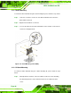
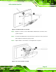
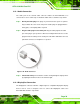
Step 5: Align the V-Stand screw holes with the pilot holes on the mounting area. Mount
the V-Stand by inserting the retention screws into the four pilot holes and
tightening them.
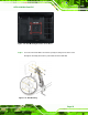
Step 6: Adjust the V-Stand to have a best viewing angle to operate the system.Step 0:
Figure 3-25: Secure V-Stand to Mounting Area
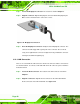
3.12 External Peripheral Device Connection
The following external peripheral devices can be connected to the external peripheral
interface connectors.
Audio devices
HDMI devices
RJ-45 Ethernet cable connector
Serial port devices
USB devices
VGA monitor
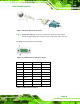
To install these devices, connect the corresponding cable connector from the actual
device to the corresponding AFL2-10A-N28 external peripheral interface connector
making sure the pins are properly aligned.