
Instruction Manual


AFL2-08A-N26
Page 40
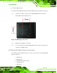
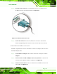
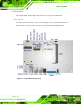
Figure 4-19: RJ-11 Serial Port Connector
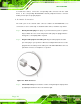
Step 4: Secure the connector. Secure the serial device connector to the external
interface by tightening the two retention screws on either side of the connector.
Ste p 0:
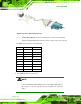
The DB-9 connector pinouts are listed below.
PIN NO. RS-422 RS-485
1 RX+ -
2 RX- -
3 TX+ D+
4 TX- D-
5 - -
6 - -
7 - -
8 - -
9 - -
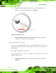
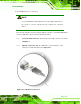
4.12.5 USB Device Connection
NOTE:
User must install the USB 3.0 driver before connecting a USB device to
the system or else the system may not recognize the connected
device.