
Instruction Manual


AFL2-08A-N26
Page 38
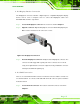
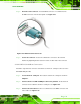
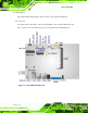
Step 2: Align the connector. Align the RJ-45 connector on the LAN cable with the
RJ-45 connector on the AFL2-08A-N26. See Figure 4-17.
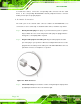
Figure 4-17: LAN Connection
Step 3: Insert the LAN cable RJ-45 connector. Once aligned, gently insert the LAN
cable RJ-45 connector into the external interface.
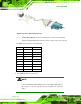
4.12.4 Serial Device Connection
There is one external RS-232 DB-9 connector and one RS-422/485 RJ-11 connector for
serial device connection. Follow the steps below to connect a serial device to the
AFL2-08A-N26.
4.12.4.1 DB-9 Serial Port Connection
Follow the steps below to connect a serial device to the DB-9 connector of the
AFL2-08A-N26 panel PC.
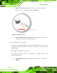
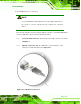
Step 1: Locate the DB-9 connector. The location of the DB-9 connector is shown in
Chapter 1.