
Instruction Manual
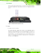


AFL2-08A-N26
Page 23
Anti-static Discharge: If a user open the rear panel of the flat bezel panel PC,
to configure the jumpers or plug in added peripheral devices, ground
themselves first and wear and anti-static wristband.
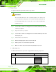
4.3 Installation and Configuration Steps
The following installation steps must be followed.
Step 1: Unpack the flat bezel panel PC.
Step 2: Install the mSATA card.
Step 3: Configure the system.
Step 4: Connect peripheral devices to the flat bezel panel PC.
Step 5: Mount the flat bezel panel PC. Step 0:
4.4 mSATA card Installation
WARNING:
Over-tightening back
cover screws will crack the plastic frame.
Maximum torque for cover screws is 5 kg-cm (0.36 lb-ft/0.49 Nm).
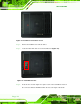
To install the mSATA card into the AFL2-08A-N26, please follow the steps below:
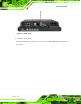
Step 1: Remove one (1) retention screw from the mSATA cover (Figure 4-1).