
Manual

AFL-xxA-N270 Series Panel PC
Page 137
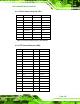
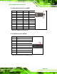
8.2.22 USB Connector (USB4)
PIN NO. DESCRIPTION
1 USB Power (selected by JP15)
2 D3F-
3 D3F+
4 GND
Table 8-23: USB Connector (USB4) Pinouts
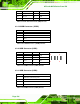
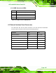
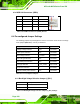
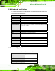
8.3 External Interface Panel Connectors
The table below lists the rear panel connectors on the AFL-xxA-N270 motherboard.
Pinouts of these connectors can be found in the following sections.
Connector Type Label
Ethernet connector RJ-45 LAN1, LAN2
Power connector DIN CN5
Reset button Push button CN6
RS-232 serial ports DB-9 COM1
RS-232/422/485 serial port DB-9 COM3
SATA connector SATA connector SATA2
USB 2.0 connectors USB 2.0 port USB3
Table 8-24: Rear Panel Connectors