
Instruction Manual

AFL-xxA-N270 Series Panel PC
Page XII
List of Figures
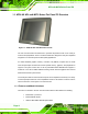
Figure 1-1: AFOLUX AFL-xxA-N270 Flat Panel PC......................................................................2
Figure 1-2: AFL-xxA-N270 Front View ..........................................................................................4
Figure 1-3: AFL-xxA-N270 Rear View ...........................................................................................5
Figure 1-4: AFL-xxA-N270 I/O Interface Connector Panel..........................................................6
Figure 1-5: AFL-xxA-N270 Top View.............................................................................................7
Figure 1-6: AFL-10A-N270 Side View............................................................................................7
Figure 2-1: AFL-07A-N270 Dimensions (mm) ............................................................................11
Figure 2-2: AFL-08AH-N270 Dimensions (mm)..........................................................................12
Figure 2-3: AFL-10A-N270 Top and Bottom Panel Dimensions (mm).....................................13
Figure 2-4: AFL-12A-N270 Top and Bottom Panel Dimensions (mm).....................................14
Figure 2-5: Preinstalled DDR2 SO-DIMM....................................................................................16
Figure 2-6: COM Ports..................................................................................................................17
Figure 2-7: RJ-45 Ethernet Connectors......................................................................................17
Figure 2-8: External USB Ports ...................................................................................................18
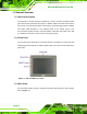
Figure 2-9: LCD Screen................................................................................................................19
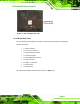
Figure 2-10: Audio Jack...............................................................................................................19
Figure 2-11: Stereo Speakers......................................................................................................20
Figure 2-12: Power Connector ....................................................................................................21
Figure 2-13: PIFA Antenna and Wireless Module......................................................................23
Figure 4-1: Back Cover Retention Screws.................................................................................32
Figure 4-2: AFL-xxA-N270 Plastic Back Cover Removal..........................................................32
Figure 4-3: CF Card Location ......................................................................................................33
Figure 4-4: AFL-08AH-N270 Plastic Back Cover Replacement................................................33
Figure 4-5: AF-12A-N270 HDD Retention Screws......................................................................34
Figure 4-6: AT/ATX Switch Location...........................................................................................35
Figure 4-7: Clear CMOS Jumper .................................................................................................39
Figure 4-8: COM1 and COM3 Pin 9 Setting Jumper Locations................................................40
Figure 4-9: COM3 RX Function Select Jumper Location..........................................................41
Figure 4-10: COM3 TX Function Select Jumper Pinout Locations..........................................42
Figure 4-11: COM3 RS-232/422/485 Serial Port Select Jumper Location................................44
Figure 4-12: Wall-mounting Bracket...........................................................................................45