
Owner's manual


Table Of Contents
- 42AFL-xxA-N270 Series Flat Panel PC
- 1 Introduction
- 2 Detailed Specifications
- 3 Unpacking
- 4 Installation
- 4.1 Anti-static Precautions
- 4.2 Installation Precautions
- 4.3 Preinstalled Components
- 4.4 Installation and Configuration Steps
- 4.5 Removing the Back Cover
- 4.6 CF Card Installation
- 4.7 HDD Installation (AF-12A-N270 Only)
- 4.8 AT/ATX Mode Selection
- 4.9 Jumper Settings
- 4.10 Mounting the System
- 4.11 Bottom Panel Connectors
- 5 System Maintenance
- 6 AMI BIOS Setup
- 7 Software Drivers
- A System Specifications
- B Safety Precautions
- C BIOS Configuration Options
- D Watchdog Timer
- E Hazardous Materials Disclosure
- F Index
AFL-xxA-N270 Series Panel PC
Page 36
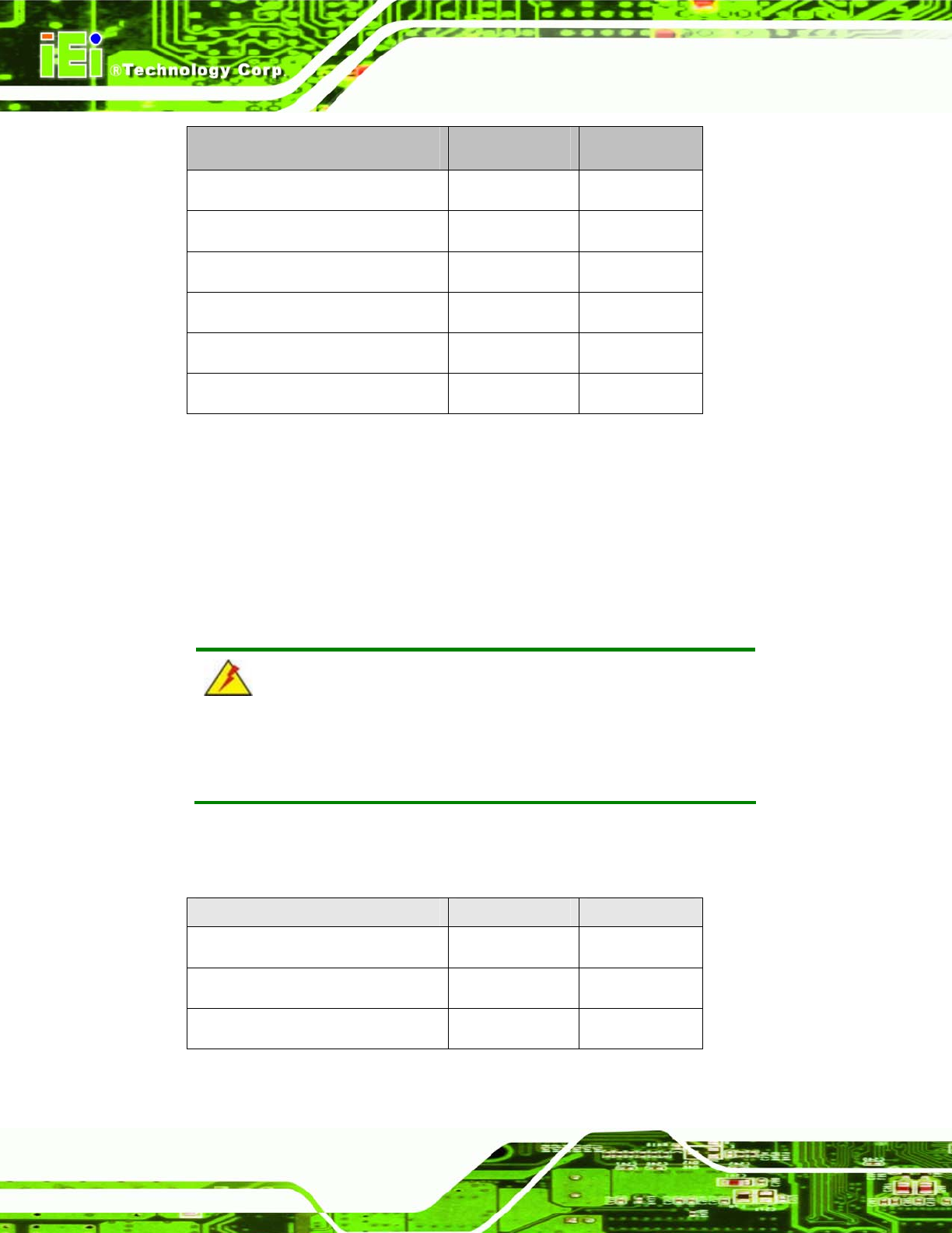
Description Label Type
Clear CMOS J_COMS1 2-pin header
COM1 Pin 9 setting JP8 10-pin header
COM3 Pin 9 setting JP10 6-pin header
COM3 RX RS-232/422/485 select JP9 8-pin header
COM3 TX RS-422/485 select JP11 6-pin header
COM3 RS-232/422/485 select JP6 12-pin header
Table 4-1: Jumpers
4.9.1 Access the Jumpers
To access the jumpers, remove the back cover. To remove the back cover, please refer to
Section
4.7 Step 1 ~ Step 4.
4.9.2 Preconfigured Jumpers
WARNING:
Do not change the settings on the jumpers in described here. Doing so
may disable or damage the system.
The following jumpers are preconfigured for the AFL-xxA-N270. Users should no change
these jumpers (
Table 4-2).
Jumper Name Label Type
LVDS voltage selection J_VLVDS1 3-pin header
Touch Screen Select J1 4-pin header
Panel Type and Resolution J_LCD_TYPE1 10-pin header
Table 4-2: Preconfigured Jumpers