
Owner's manual


Table Of Contents
- 42AFL-xxA-N270 Series Flat Panel PC
- 1 Introduction
- 2 Detailed Specifications
- 3 Unpacking
- 4 Installation
- 4.1 Anti-static Precautions
- 4.2 Installation Precautions
- 4.3 Preinstalled Components
- 4.4 Installation and Configuration Steps
- 4.5 Removing the Back Cover
- 4.6 CF Card Installation
- 4.7 HDD Installation (AF-12A-N270 Only)
- 4.8 AT/ATX Mode Selection
- 4.9 Jumper Settings
- 4.10 Mounting the System
- 4.11 Bottom Panel Connectors
- 5 System Maintenance
- 6 AMI BIOS Setup
- 7 Software Drivers
- A System Specifications
- B Safety Precautions
- C BIOS Configuration Options
- D Watchdog Timer
- E Hazardous Materials Disclosure
- F Index
AFL-xxA-N270 Series Panel PC
Page 121
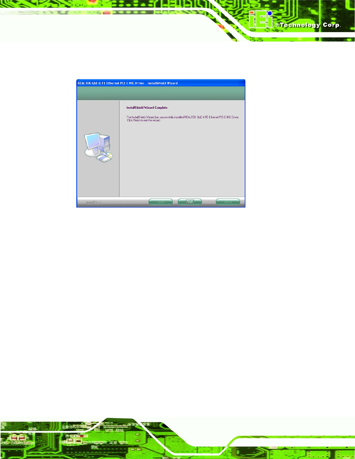
Step 9: When the driver installation is complete, the screen in Figure 7-23 appears.
Step 0:
Figure 7-23: LAN Driver Installation Complete
7.7 Touch Screen Driver
To install the touch panel software driver, please follow the steps below.
Step 1: Access the driver list shown in
Figure 7-1. (See Section 7.2)
Step 2: Click “Touch Screen”. Open the x:\Touch\PenMount Windows Universal
Driver V2.0.0.107 directory and locate the icon for the Setup.exe installation file.
Once located, use the mouse to double click the icon.
Step 3: A welcome screen appears (
Figure 7-24). To continue the installation process
click N
EXT.