
Owner's manual


Table Of Contents
- 42AFL-xxA-N270 Series Flat Panel PC
- 1 Introduction
- 2 Detailed Specifications
- 3 Unpacking
- 4 Installation
- 4.1 Anti-static Precautions
- 4.2 Installation Precautions
- 4.3 Preinstalled Components
- 4.4 Installation and Configuration Steps
- 4.5 Removing the Back Cover
- 4.6 CF Card Installation
- 4.7 HDD Installation (AF-12A-N270 Only)
- 4.8 AT/ATX Mode Selection
- 4.9 Jumper Settings
- 4.10 Mounting the System
- 4.11 Bottom Panel Connectors
- 5 System Maintenance
- 6 AMI BIOS Setup
- 7 Software Drivers
- A System Specifications
- B Safety Precautions
- C BIOS Configuration Options
- D Watchdog Timer
- E Hazardous Materials Disclosure
- F Index
AFL-xxA-N270 Series Panel PC
Page 97
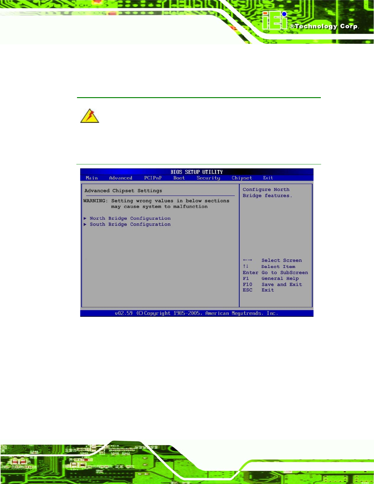
6.7 Chipset
Use the Chipset menu (6BIOS Menu 17) to access the NorthBridge and SouthBridge
configuration menus
WARNING!
Setting the wrong values for the Chipset BIOS selections in the Chipset BIOS
menu may cause the system to malfunction.
BIOS Menu 17: Chipset
6.7.1 North Bridge Chipset Configuration
Use the North Bridge Chipset Configuration menu (BIOS Menu 18) to configure the
Northbridge chipset settings.