
User Manual

AFL-W19A/W19B/17D/W15A-N270 Panel PC
Page 40
Step 1: Locate the RJ-45 connector on the bottom panel of the
AFL-W19A/W19B/17D/W15A-N270.
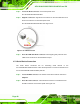
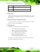
Step 2: Align the connectors. Align the RJ-45 connector on the LAN cable with one of
the RJ-45 connectors on the bottom panel of the
AFL-W19A/W19B/17D/W15A-N270. See
Figure 2-30..
Figure 2-30: LAN Connection
Step 3: Insert the LAN cable RJ-45 connector. Once aligned, gently insert the LAN
cable RJ-45 connector into the onboard RJ-45 port. Step 0:
2.7.2 Serial Device Connection
The serial device connectors are for connecting serial devices to the
AFL-W19A/W19B/17D/W15A-N270. Follow the steps below to connect a serial device to
the AFL-W19A/W19B/17D/W15A-N270 panel PC.
Step 1: Locate the DB-9 connector. The location of the DB-9 connector is shown in
Chapter 2.
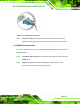
Step 2: Insert the serial connector. Insert the DB-9 connector of a serial device into
the DB-9 connector on the bottom panel. See
Figure 2-31.