
Instruction Manual

AFL-W19A/W19B/17D/W15A-GM45 Panel PC
Page 25
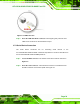
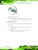
Figure 2-10: USB Device Connection
Step 3: Insert the device connector. Once aligned, gently insert the USB device
connector into the onboard connector. Step 0:
2.7.4 VGA Monitor Connection
The VGA output can be connected to an external VGA monitor. To connect the VGA
monitor to the AFL-W19A/W19B/17D/W15A-GM45, please follow the instructions below.
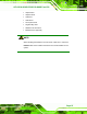
Step 1: Locate the female DB-15 connector. The location of the female DB-15
connector is shown in
5Figure 2-7.
Step 2: Align the VGA connector. Align the male DB-15 connector on the VGA screen
cable with the female DB-15 connector on the external peripheral interface.
Step 3: Insert the VGA connector. Once the connectors are properly aligned with the
insert the male connector from the VGA screen into the female connector on the
AFL-W19A/W19B/17D/W15A-GM45. See
5Figure 2-11.