
Instruction Manual

AFL-W19A/W19B/17D/W15A-GM45 Panel PC
Page 19
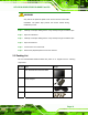
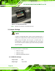
Jumper Settings:
See
5Table 2-2
The pin-9 signal can be selected as 12 V, 5 V or Ring.
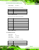
Pin Description
1-3 12 V
3-5 5 V
7-9 RI
Table 2-2: COM1 Pin-9 Setup
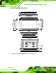
The pinouts for the COM1 connector are shown below.
Pin Description
1 DCD
2 RX
3 TX
4 DTR
5 GND
6 DSR
7 RTS
8 CTS
9 RI
Table 2-3: COM1 Pinouts
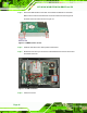
2.5.2 COM3 Pin-9 Setup
Jumper Label: J5
Jumper Type:
10-pin header
Jumper Settings:
See
5Table 2-4
The pin-9 signal can be selected as 12 V, 5 V or Ring.
Pin Description
1-2 12 V
3-4 RI