
User guide


AFL-W10A-N270 User Manual
Page 92
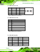
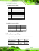
5.2.20 USB Connector (USB1)
PIN NO. DESCRIPTION PIN NO. DESCRIPTION
1 +5Vsus 2 GND
3 D0F- 4 D0F+
5 D0F+ 6 D0F-
7 GND 8 +5Vsus
2 8
y y y y
y y y y
1 7
Table 5-21: USB Connector (USB1) Pinouts
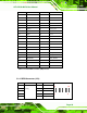
5.2.21 USB Connector (USB2)
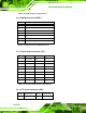
5.2.22 USB Connector (USB4)
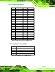
5.3 External
Interface Panel Connectors
The table below lists the rear panel connectors on the AFL-W10A-N270 motherboard.
Pinouts of these connectors can be found in the following sections.
PIN NO. DESCRIPTION
1 USB Power (selected by JP15)
2 D2F-
3 D2F+
4 GND
Table 5-22: USB Connector (USB2) Pinouts
PIN NO. DESCRIPTION
1 USB Power (selected by JP15)
2 D3F-
3 D3F+
4 GND
Table 5-23: USB Connector (USB4) Pinouts