
User guide


AFL-W10A-N270 User Manual
Page 87
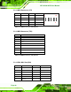
Table 5-9: DIO Connector (DIO1) Pinouts
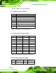
5.2.9 HDD Power Connector (CN1)
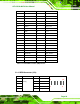
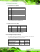
5.2.10 LED Indicator and Button Connector (JP2)
PIN NO. DESCRIPTION PIN NO.
DESCRIPTION
1 PW_LED +5V 2 +5V
3 GND 4 HD_LED
5 SUS PW LED +5V
6 RST_SW
7 GND 8 GND
9 PW_BN 10 GND
2 10
y y y y y
y y y y y
1 9
Table 5-11: LED Indicator and Button Connector (JP2) Pinouts
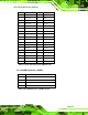
5.2.11 LVDS Backlight Connector (INVERTER1)
PIN NO. DESCRIPTION
1 +5V
2 GND
3 GND
4 +12V
Table 5-10: HDD Power Connector (CN1) Pinouts
PIN NO. DESCRIPTION
1 +12V
2 +12V
3 BLON
4 BRIGHTNESS
5 GND
6 GND
Table 5-12: LVDS Backlight Connector (INVERTER1) Pinouts