
Instruction Manual


AFL-W10A-N270 User Manual
Page 43
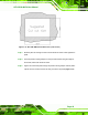
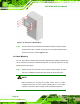
Figure 2-13: AFL-15B-AM2 Cutout Dimensions (units in mm)
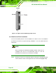
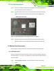
Step 3: Slide the panel PC through the hole until the aluminum frame is flush against the
panel.
Step 4: Insert the panel mounting clamps into the pre-formed holes along the edges of
the chassis, behind the aluminum frame.
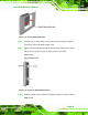
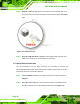
Step 5: Tighten the screws that pass through the panel mounting clamps until the plastic
caps at the front of all the screws are firmly secured to the panel (Figure 2-14).
Step 0: