
Owner manual

AFL-W10A-N270 User Manual
Page 45
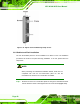
Step 2: Once the mounting arm has been firmly attached to the surface, lift the panel PC
onto the interface pad of the mounting arm.
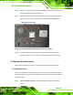
Step 3: Align the retention screw holes on the mounting arm interface with those in the
panel PC. The arm mount retention screw holes are shown in
Figure 2-18.
Figure 2-18:AFL-W10A-N270 Arm Mounting Retention Screw Holes
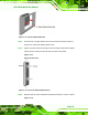
Step 4: Secure the panel PC to the interface pad by inserting the retention screws
through the bottom of the mounting arm interface pad and into the panel PC.
Step 0:
2.7 Bottom Panel Connectors
All I/O interface connections of the AFL-W10A-N270 are found on the bottom panel.
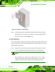
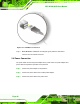
2.7.1 LAN Connection
There is one external RJ-45 LAN connector. The RJ-45 connector enables connection to
an external network. To connect a LAN cable with an RJ-45 connector, please follow the
instructions below.
Step 1: Locate the RJ-45 connector on the bottom panel of the AFL-W10A-N270
Series.