
Owner manual


AFL-W10A-N270 User Manual
Page 32
Load Failsafe Defaults.
After having done one of the above, save the changes and exit the CMOS Setup menu.
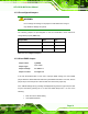
The clear CMOS jumper settings are shown in Table 2-3.
Clear CMOS Description
Short 1 - 2 Keep CMOS Setup Default
Short 2 - 3 Clear CMOS Setup
Table 2-3: Clear CMOS Jumper Settings
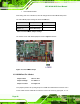
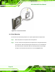
The location of the clear CMOS jumper is shown in Figure 2-5 below.
Figure 2-5: Clear CMOS Jumper
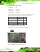
2.5.4 COM Port Pin 9 Select
Jumper Label:
JP8 and JP10
Jumper Settings:
See
Table 2-4
Jumper Location:
See
Figure 2-6
Two jumpers (JP8 and JP10) configure pin 9 on COM1 and COM3 DB-9 connectors. Pin 9
on the COM1 and the COM3 DB-9 connectors can be set as the ring (RI) signal, +5 V or