
User Manual
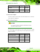


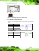


Table Of Contents
- 1 Introduction
- 2 Unpacking
- 3 Installation
- 4 System Maintenance
- 5 AMI BIOS Setup
- 5.1 Introduction
- 5.2 Main
- 5.3 Advanced
- 5.4 iEi Feature
- 5.5 Chipset
- 5.6 Boot
- 5.7 Security
- 5.8 Save & Exit
- 6 Software Drivers
- 7 Interface Connectors
- 7.1 Peripheral Interface Connectors
- 7.2 Internal Peripheral Connectors
- 7.2.1 Audio Speaker-out Connector (CN3)
- 7.2.2 Audio MIC-in Connector (MIC1)
- 7.2.3 Audio DMIC-in Connector (DMIC1)
- 7.2.4 Battery Connector (CN1)
- 7.2.5 COM2 Connector (COM2)
- 7.2.6 CPU Fan Connector (CPU_FAN1)
- 7.2.7 DIO Connector (DIO1)
- 7.2.8 HDD LED Connector (HDD_CN1)
- 7.2.9 I2C Connector (CN4)
- 7.2.10 LVDS Connector (LVDS1)
- 7.2.11 LVDS Backlight Connector (INVERTER1)
- 7.2.12 MCU Connector (JP8)
- 7.2.13 MCU Connector (HOTKEY_CN1)
- 7.2.14 PCIe Mini Slot (M_PCIE1)
- 7.2.15 PCIe Mini Slot (M_PCIE2)
- 7.2.16 Power LED Connector (PW_LED1)
- 7.2.17 Power Button Connector (PW_BTN1)
- 7.2.18 SATA Power Connector (SATA_PWR1)
- 7.2.19 SATA Connector (SATA1)
- 7.2.20 Touch Panel Connector (TS1)
- 7.2.21 TTL Panel Connector (CN6)
- 7.2.22 USB Connector (USB1)
- 7.2.23 USB Connector (USB2)
- 7.2.24 USB Connector (USB3)
- 7.2.25 USB2 and USB3 Power Connector (JP18)
- 7.3 External Interface Panel Connectors
- 7.4 Preconfigured Jumper Settings
- A Safety Precautions
- B BIOS Configuration Options
- C Watchdog Timer
- D Hazardous Materials Disclosure
AFL-xxA-N26 Series Panel PC
Page 44
3.8.3 Clear CMOS Jumper
Jumper Label:
JP2
Jumper Type:
3-pin header
Jumper Settings:
See
Table 3-3
Jumper Location:
See
Figure 3-13
If the AFL-xxA-N26 fails to boot due to improper BIOS settings, the clear CMOS jumper
clears the CMOS data and resets the system BIOS information. To do this, use the jumper
cap to close the pins for a few seconds then remove the jumper clip.
If the “CMOS Settings Wrong” message is displayed during the boot up process, the fault
may be corrected by pressing the F1 to enter the CMOS Setup menu. Do one of the
following:
Enter the correct CMOS setting
Load Optimal Defaults
Load Failsafe Defaults.
After having done one of the above, save the changes and exit the CMOS Setup menu.
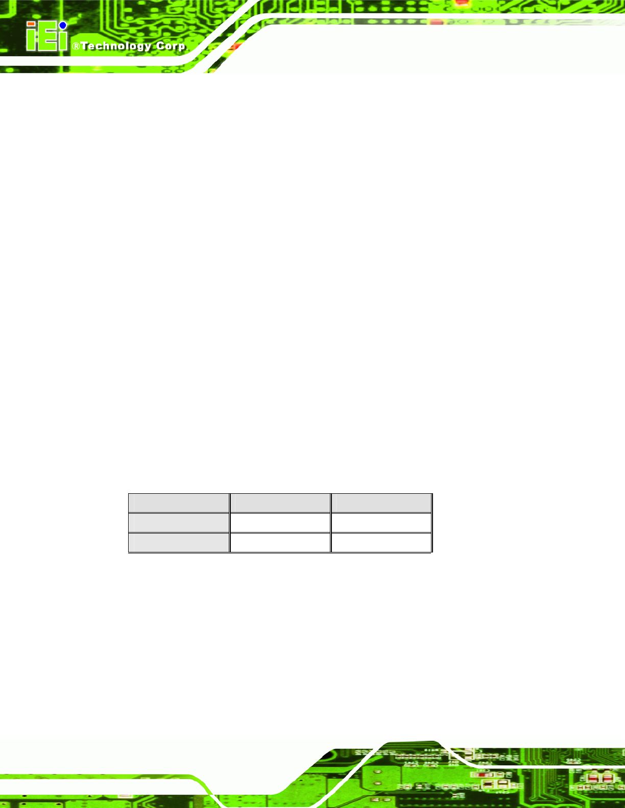
The clear CMOS jumper settings are shown in
Table 3-3.
Clear CMOS Description
Short 1 - 2 Keep CMOS Setup Default
Short 2 - 3 Clear CMOS Setup
Table 3-3: Clear CMOS Jumper Settings
The location of the clear CMOS jumper is shown in Figure 3-13 below.