
User Manual
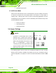


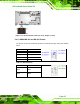


Table Of Contents
- 1 Introduction
- 2 Unpacking
- 3 Installation
- 4 System Maintenance
- 5 AMI BIOS Setup
- 5.1 Introduction
- 5.2 Main
- 5.3 Advanced
- 5.4 iEi Feature
- 5.5 Chipset
- 5.6 Boot
- 5.7 Security
- 5.8 Save & Exit
- 6 Software Drivers
- 7 Interface Connectors
- 7.1 Peripheral Interface Connectors
- 7.2 Internal Peripheral Connectors
- 7.2.1 Audio Speaker-out Connector (CN3)
- 7.2.2 Audio MIC-in Connector (MIC1)
- 7.2.3 Audio DMIC-in Connector (DMIC1)
- 7.2.4 Battery Connector (CN1)
- 7.2.5 COM2 Connector (COM2)
- 7.2.6 CPU Fan Connector (CPU_FAN1)
- 7.2.7 DIO Connector (DIO1)
- 7.2.8 HDD LED Connector (HDD_CN1)
- 7.2.9 I2C Connector (CN4)
- 7.2.10 LVDS Connector (LVDS1)
- 7.2.11 LVDS Backlight Connector (INVERTER1)
- 7.2.12 MCU Connector (JP8)
- 7.2.13 MCU Connector (HOTKEY_CN1)
- 7.2.14 PCIe Mini Slot (M_PCIE1)
- 7.2.15 PCIe Mini Slot (M_PCIE2)
- 7.2.16 Power LED Connector (PW_LED1)
- 7.2.17 Power Button Connector (PW_BTN1)
- 7.2.18 SATA Power Connector (SATA_PWR1)
- 7.2.19 SATA Connector (SATA1)
- 7.2.20 Touch Panel Connector (TS1)
- 7.2.21 TTL Panel Connector (CN6)
- 7.2.22 USB Connector (USB1)
- 7.2.23 USB Connector (USB2)
- 7.2.24 USB Connector (USB3)
- 7.2.25 USB2 and USB3 Power Connector (JP18)
- 7.3 External Interface Panel Connectors
- 7.4 Preconfigured Jumper Settings
- A Safety Precautions
- B BIOS Configuration Options
- C Watchdog Timer
- D Hazardous Materials Disclosure
AFL-xxA-N26 Series Panel PC
Page 41
WARNING:
Over-tightening back cover screws will crack the plastic frame.
Maximum torque for cover screws is 5 kg-cm (0.36 lb-ft/0.49 Nm).
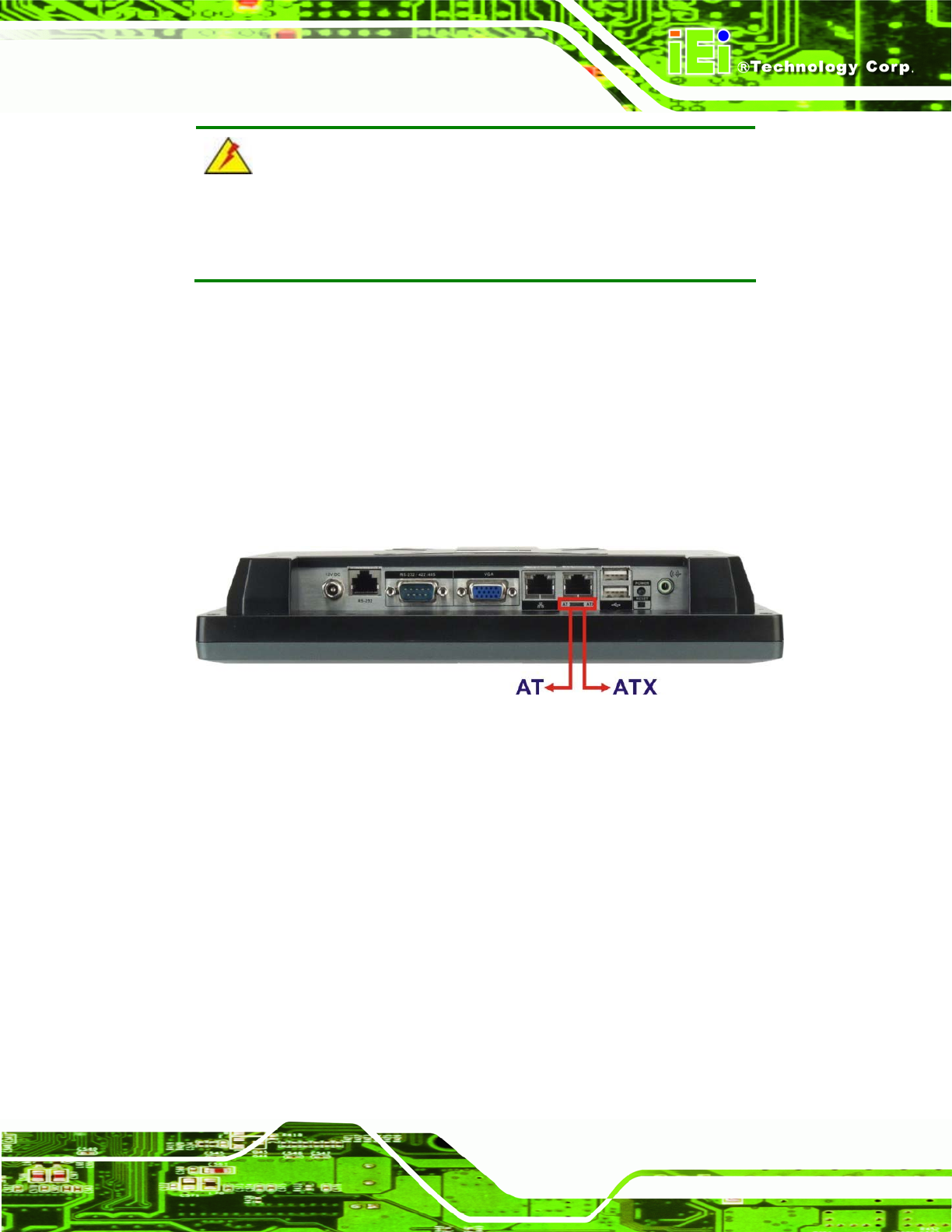
3.7 AT/ATX Mode Selection
AT and ATX power modes can both be used on the AFL-xxA-N26 series. The selection is
made through an AT/ATX switch on the bottom panel (
Figure 3-12). To select AT mode or
ATX mode, follow the steps below.
Step 1: Locate the AT/ATX switch on the bottom panel (
Figure 3-12).
Figure 3-12: AT/ATX Switch Location
Step 2: Adjust the AT/ATX switch. Step 0:
3.7.1 AT Power Mode
With the AT mode selected, the power is controlled by a central power unit rather than a
power switch. The AFL-xxA-N26 panel PC turns on automatically when the power is
connected. The AT mode benefits a production line to control multiple panel PCs from a
central management center and other applications including:
ATM
Self-service kiosk
Plant environment monitoring system
Factory automation platform