
User Manual
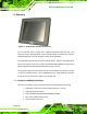

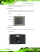

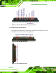
Table Of Contents
- 1 Introduction
- 2 Unpacking
- 3 Installation
- 4 System Maintenance
- 5 AMI BIOS Setup
- 5.1 Introduction
- 5.2 Main
- 5.3 Advanced
- 5.4 iEi Feature
- 5.5 Chipset
- 5.6 Boot
- 5.7 Security
- 5.8 Save & Exit
- 6 Software Drivers
- 7 Interface Connectors
- 7.1 Peripheral Interface Connectors
- 7.2 Internal Peripheral Connectors
- 7.2.1 Audio Speaker-out Connector (CN3)
- 7.2.2 Audio MIC-in Connector (MIC1)
- 7.2.3 Audio DMIC-in Connector (DMIC1)
- 7.2.4 Battery Connector (CN1)
- 7.2.5 COM2 Connector (COM2)
- 7.2.6 CPU Fan Connector (CPU_FAN1)
- 7.2.7 DIO Connector (DIO1)
- 7.2.8 HDD LED Connector (HDD_CN1)
- 7.2.9 I2C Connector (CN4)
- 7.2.10 LVDS Connector (LVDS1)
- 7.2.11 LVDS Backlight Connector (INVERTER1)
- 7.2.12 MCU Connector (JP8)
- 7.2.13 MCU Connector (HOTKEY_CN1)
- 7.2.14 PCIe Mini Slot (M_PCIE1)
- 7.2.15 PCIe Mini Slot (M_PCIE2)
- 7.2.16 Power LED Connector (PW_LED1)
- 7.2.17 Power Button Connector (PW_BTN1)
- 7.2.18 SATA Power Connector (SATA_PWR1)
- 7.2.19 SATA Connector (SATA1)
- 7.2.20 Touch Panel Connector (TS1)
- 7.2.21 TTL Panel Connector (CN6)
- 7.2.22 USB Connector (USB1)
- 7.2.23 USB Connector (USB2)
- 7.2.24 USB Connector (USB3)
- 7.2.25 USB2 and USB3 Power Connector (JP18)
- 7.3 External Interface Panel Connectors
- 7.4 Preconfigured Jumper Settings
- A Safety Precautions
- B BIOS Configuration Options
- C Watchdog Timer
- D Hazardous Materials Disclosure
AFL-xxA-N26 Series Panel PC
Page 18
provides access to external interface connectors that include LAN, USB 2.0, serial port,
reset button, power connector and power switch.
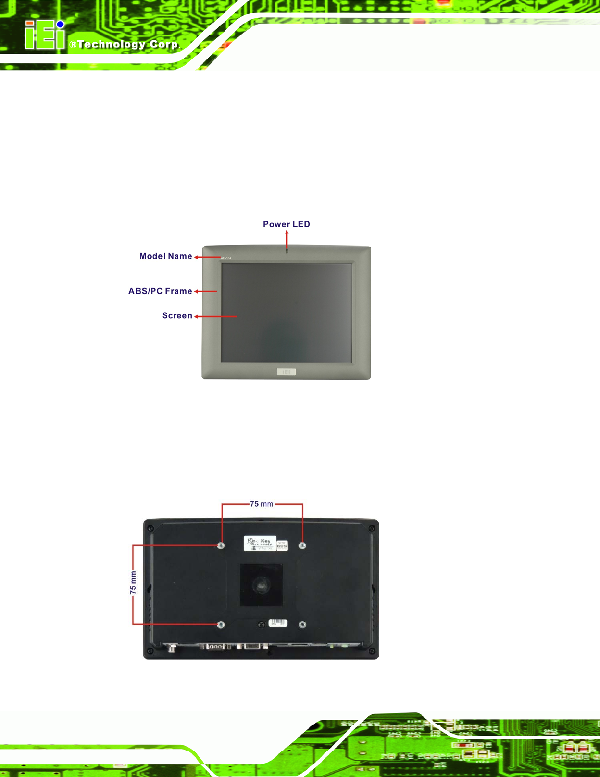
1.2.1 Front Panel
The front side of the AFOLUX AFL-xxA-N26 series is a flat panel TFT LCD screen with
LED backlight surrounded by an ABS/PC plastic frame. The top of the front panel has a
power LED.
Figure 1-2: AFL-xxA-N26 Front View
1.2.2 Rear Panel
The rear panel provides access to retention screw holes that support VESA mounting.
Refer to
Figure 1-3.
Figure 1-3: AFL-xxA-N26 Rear View