
User Manual

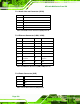


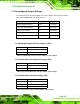
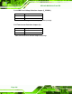
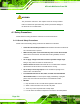
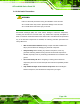
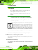
Table Of Contents
- 1 Introduction
- 2 Unpacking
- 3 Installation
- 4 System Maintenance
- 5 AMI BIOS Setup
- 5.1 Introduction
- 5.2 Main
- 5.3 Advanced
- 5.4 iEi Feature
- 5.5 Chipset
- 5.6 Boot
- 5.7 Security
- 5.8 Save & Exit
- 6 Software Drivers
- 7 Interface Connectors
- 7.1 Peripheral Interface Connectors
- 7.2 Internal Peripheral Connectors
- 7.2.1 Audio Speaker-out Connector (CN3)
- 7.2.2 Audio MIC-in Connector (MIC1)
- 7.2.3 Audio DMIC-in Connector (DMIC1)
- 7.2.4 Battery Connector (CN1)
- 7.2.5 COM2 Connector (COM2)
- 7.2.6 CPU Fan Connector (CPU_FAN1)
- 7.2.7 DIO Connector (DIO1)
- 7.2.8 HDD LED Connector (HDD_CN1)
- 7.2.9 I2C Connector (CN4)
- 7.2.10 LVDS Connector (LVDS1)
- 7.2.11 LVDS Backlight Connector (INVERTER1)
- 7.2.12 MCU Connector (JP8)
- 7.2.13 MCU Connector (HOTKEY_CN1)
- 7.2.14 PCIe Mini Slot (M_PCIE1)
- 7.2.15 PCIe Mini Slot (M_PCIE2)
- 7.2.16 Power LED Connector (PW_LED1)
- 7.2.17 Power Button Connector (PW_BTN1)
- 7.2.18 SATA Power Connector (SATA_PWR1)
- 7.2.19 SATA Connector (SATA1)
- 7.2.20 Touch Panel Connector (TS1)
- 7.2.21 TTL Panel Connector (CN6)
- 7.2.22 USB Connector (USB1)
- 7.2.23 USB Connector (USB2)
- 7.2.24 USB Connector (USB3)
- 7.2.25 USB2 and USB3 Power Connector (JP18)
- 7.3 External Interface Panel Connectors
- 7.4 Preconfigured Jumper Settings
- A Safety Precautions
- B BIOS Configuration Options
- C Watchdog Timer
- D Hazardous Materials Disclosure
AFL-xxA-N26 Series Panel PC
Page 131
7.2.24 USB Connector (USB3)
7.2.25 USB2 and USB3 Power Connector (JP18)
PIN NO. DESCRIPTION PIN NO. DESCRIPTION
1 +3.3V 2 +3.3V
3 GND 4 GND
5 +5V 6 +5V
Table 7-26: USB2 and USB3 Power Connector (JP18) Pinouts
7.3 External Interface Panel Connectors
The table below lists the rear panel connectors on the AFL-xxA-N26 motherboard. Pinouts
of these connectors can be found in the following sections.
Connector Type Label
Audio line-out connector Audio jack AUX1
Ethernet connector RJ-45 LAN1, LAN2
Power connector Power jack CN5
Reset button Push button RST1
RS-232 serial ports RJ-45 COM1
RS-232/422/485 serial port DB-9 COM3
USB 2.0 connectors USB 2.0 port USB3
VGA connector DB-15 VGA1
Table 7-27: Rear Panel Connectors
PIN NO. DESCRIPTION
1 +5Vsus
2 D3F-
3 D3F+
4 GND
Table 7-25: USB Connector (USB3) Pinouts