
User Manual
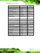
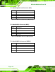
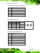

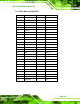


Table Of Contents
- 1 Introduction
- 2 Unpacking
- 3 Installation
- 4 System Maintenance
- 5 AMI BIOS Setup
- 5.1 Introduction
- 5.2 Main
- 5.3 Advanced
- 5.4 iEi Feature
- 5.5 Chipset
- 5.6 Boot
- 5.7 Security
- 5.8 Save & Exit
- 6 Software Drivers
- 7 Interface Connectors
- 7.1 Peripheral Interface Connectors
- 7.2 Internal Peripheral Connectors
- 7.2.1 Audio Speaker-out Connector (CN3)
- 7.2.2 Audio MIC-in Connector (MIC1)
- 7.2.3 Audio DMIC-in Connector (DMIC1)
- 7.2.4 Battery Connector (CN1)
- 7.2.5 COM2 Connector (COM2)
- 7.2.6 CPU Fan Connector (CPU_FAN1)
- 7.2.7 DIO Connector (DIO1)
- 7.2.8 HDD LED Connector (HDD_CN1)
- 7.2.9 I2C Connector (CN4)
- 7.2.10 LVDS Connector (LVDS1)
- 7.2.11 LVDS Backlight Connector (INVERTER1)
- 7.2.12 MCU Connector (JP8)
- 7.2.13 MCU Connector (HOTKEY_CN1)
- 7.2.14 PCIe Mini Slot (M_PCIE1)
- 7.2.15 PCIe Mini Slot (M_PCIE2)
- 7.2.16 Power LED Connector (PW_LED1)
- 7.2.17 Power Button Connector (PW_BTN1)
- 7.2.18 SATA Power Connector (SATA_PWR1)
- 7.2.19 SATA Connector (SATA1)
- 7.2.20 Touch Panel Connector (TS1)
- 7.2.21 TTL Panel Connector (CN6)
- 7.2.22 USB Connector (USB1)
- 7.2.23 USB Connector (USB2)
- 7.2.24 USB Connector (USB3)
- 7.2.25 USB2 and USB3 Power Connector (JP18)
- 7.3 External Interface Panel Connectors
- 7.4 Preconfigured Jumper Settings
- A Safety Precautions
- B BIOS Configuration Options
- C Watchdog Timer
- D Hazardous Materials Disclosure
AFL-xxA-N26 Series Panel PC
Page 129
7.2.20 Touch Panel Connector (TS1)
7.2.21 TTL Panel Connector (CN6)
PIN NO. DESCRIPTION PIN NO.
DESCRIPTION
1 GND 21 TFT_G5
2 GND 22 TFT_G4
3 TTL_VSYNC 23 TFT_G3
4 TTL_VCC3 24 GND
5 TTL_VCC3 25 TFT_G2
6 TTL_VCC3 26 TFT_G1
7 TTL_VCC3 27 TFT_G0
8 TTL_HSYNC 28 GND
9 LCD_EN 29 TFT_R5
10 GND 30 TFT_R4
11 GND 31 TFT_R3
12 GND 32 GND
13 TFT_B5 33 TFT_R2
14 TFT_B4 34 TFT_R1
15 TFT_B3 35 TFT_R0
16 GND 36 GND
PIN NO. 8-Wire 4-Wire 5-Wire
1 Right Sense N/A N/A
2 Left Sense N/A N/A
3 Bottom Sense N/A N/A
4 Top Sense N/A Sense (S)
5 Right Excite Right LR (X)
6 Left Excite Left LL (L)
7 Bottom Excite Bottom UR (H)
8 Top Excite Top UL (Y)
9 GND GND GND
Table 7-21: Touch Panel Connector (TS1) Pinouts