AFL-4 Series-N270 User Manual AFL-4xxx Series ATOM MODEL: AFL-4 Series-N270 In-wall Panel PC with Touch Screen and Intel® Atom™ CPU Gigabit Ethernet, Five USB, Audio, RS-232/422/485, RoHS Compliant, IP64 Protection User Manual Page 1 Rev. 2.
AFL-4 Series-N270 User Manual Revision Date Version Changes 29 June, 2011 2.
AFL-4 Series-N270 User Manual Copyright COPYRIGHT NOTICE The information in this document is subject to change without prior notice in order to improve reliability, design and function and does not represent a commitment on the part of the manufacturer. In no event will the manufacturer be liable for direct, indirect, special, incidental, or consequential damages arising out of the use or inability to use the product or documentation, even if advised of the possibility of such damages.
AFL-4 Series-N270 User Manual Packing List NOTE: If any of the components listed in the checklist below are missing, please do not proceed with the installation. Contact the IEI reseller or vendor you purchased the AFL-4 Series-N270 from or contact an IEI sales representative directly. To contact an IEI sales representative, please send an email to sales@iei.com.tw. The items listed below should all be included in the AFL-4 Series-N270 package.
AFL-4 Series-N270 User Manual Table of Contents 1 INTRODUCTION........................................................................................................ 16 1.1 AFL-4 SERIES-N270 FLAT PANEL PC OVERVIEW..................................................... 16 1.1.1 Features ........................................................................................................... 17 1.1.2 Applications ...............................................................................................
AFL-4 Series-N270 User Manual 2.5.3 External USB Connectors ................................................................................ 32 2.6 AC’97 AUDIO CODEC CONTROLLER ........................................................................ 32 2.7 SYSTEM POWER ....................................................................................................... 32 2.7.1.1 ATX Power Mode (Default)...................................................................... 33 2.7.1.2 AT Power Mode .......
AFL-4 Series-N270 User Manual 4.9.8 LCD Panel Type Jumper .................................................................................. 56 4.9.9 MCU LCD Panel Select Jumper ...................................................................... 57 4.9.10 MCU LCD Type Select Jumper ...................................................................... 58 4.9.11 Touch Screen Select ........................................................................................ 59 4.10 MOUNTING THE SYSTEM ........
AFL-4 Series-N270 User Manual 6.3.1 CPU Configuration.......................................................................................... 84 6.3.2 IDE Configuration ........................................................................................... 85 6.3.2.1 IDE Master, IDE Slave ............................................................................. 86 6.3.3 Super I/O Configuration .................................................................................. 90 6.3.
AFL-4 Series-N270 User Manual A TERMINOLOGY...................................................................................................... 150 B WATCHDOG TIMER............................................................................................... 154 C COMPATIBILITY .................................................................................................... 157 C.1 COMPATIBLE OPERATING SYSTEMS ....................................................................... 158 C.
AFL-4 Series-N270 User Manual List of Figures Figure 1-1: AFL-4 Series-N270 Flat Panel PC ............................................................................16 Figure 1-2: AFL-4 Series-N270 Front View .................................................................................18 Figure 1-3: AFL-4 Series-N270 Rear View ..................................................................................19 Figure 1-4: AFL-4 Series Interface Connector Panel .........................................
AFL-4 Series-N270 User Manual Figure 4-19: Attach Foam Tape ...................................................................................................64 Figure 4-20: Foam Tape Installed................................................................................................64 Figure 4-21: AFL-408A/B-N270 In-wall Panel Opening .............................................................65 Figure 4-22: AFL-W410A-N270 In-wall Opening ............................................................
AFL-4 Series-N270 User Manual Figure 7-21: Installation Wizard Updates the System............................................................ 129 Figure 7-22: Restart the Computer .......................................................................................... 129 Figure 7-23: LAN Driver Welcome Screen .............................................................................. 130 Figure 7-24: LAN Driver Welcome Screen ............................................................................
AFL-4 Series-N270 User Manual Figure 7-56: Software Installation Alert................................................................................... 148 Figure 7-57: Installation Complete...........................................................................................
AFL-4 Series-N270 User Manual List of Tables Table 1-1: AFL-4 Series-N270 Specifications ............................................................................23 Table 4-1: Jumpers .......................................................................................................................49 Table 4-2: ATX/AT Power Mode Jumper Settings .....................................................................50 Table 4-3: Clear CMOS Jumper Settings................................................
AFL-4 Series-N270 User Manual BIOS Menus BIOS Menu 1: Main .......................................................................................................................82 BIOS Menu 2: Advanced ..............................................................................................................84 BIOS Menu 3: CPU Configuration ...............................................................................................84 BIOS Menu 4: IDE Configuration....................................
AFL-4 Series-N270 User Manual Chapter 1 1 Introduction 1.1 AFL-4 Series-N270 Flat Panel PC Overview Figure 1-1: AFL-4 Series-N270 Flat Panel PC The AFL-4 Series-N270 models are Intel® Atom™ powered flat panel PCs with a rich variety of functions and peripherals.
AFL-4 Series-N270 User Manual and simplified integration in conference center, home automation, and building control applications. An Intel® 945GSE graphics memory controller hub (GMCH) coupled with an Intel® ICH7M input/output controller hub ensures optimal memory, graphics, and peripheral I/O support. The system comes with 1.0 GB of preinstalled DDR2 SDRAM and supports a maximum of 2.0 GB of DDR2 SDRAM ensuring smooth data throughputs with reduced bottlenecks and fast system access.
AFL-4 Series-N270 User Manual 1.2 External Overview The stylish AFL-4 Series-N270 panel PC comprises of a screen, rear panel, top panel, bottom panel and two side panels (left and right). An ABS/PC plastic front frame surrounds the front screen. The rear panel provides screw holes for a wall-mounting bracket compliant with VESA FDMI standard. An I/O interface panel on the bottom panel of the AFL-4 Series-N270 provides access to external interface connectors that include LAN, USB 2.
AFL-4 Series-N270 User Manual 1.2.2 Rear Panel The rear panel provides access to the internal components of the AFL-4 Series-N270 and CF card slot. Refer to Figure 1-3 for back cover retention screw, VESA mount screw holes and CompactFlash® slot locations. Figure 1-3: AFL-4 Series-N270 Rear View 1.2.
AFL-4 Series-N270 User Manual 1 x LAN connectors 4 x USB 2.0 connectors 1 x AT/ATX mode select 1 x Digital Input/Output The external I/O interface connector panel is shown in Figure 1-4. Figure 1-4: AFL-4 Series Interface Connector Panel 1.3 Internal Overview The AFL-4 Series-N270 has the following components installed internally: Page 20 1 x Motherboard 1 x 1.
AFL-4 Series-N270 User Manual 1.4 System Specifications The technical specifications for the AFL-4 Series-N270 systems are listed below in Table 1-1. 8.4" 8.0" 10.2" 12.
AFL-4 Series-N270 User Manual AFL-415AE-N270 AFL-415A-N270 AFL-412A-N270 AFL-W410A-N270 AFL-408B-N270 RAM AFL-408A-N270 Specifications Supports one 400MHz or 533MHz DDR2 SO-DIMM (2GB Max.) One DC-IN terminal block One Power jack Two Power switches One Reset button I/O Ports and Switches One DI/O (4-input / 4-output) One RJ-45 for Giga LAN One RJ-45 port for RS-232 One RJ-45 port for RS-232/422/485 Four USB 2.0 ports, bottom panel One USB 2.
AFL-4 Series-N270 User Manual Panel, Wall, VESA 75mm x 75mm / 100mm x 100mm Front Panel Color Black (Black U), White (Apple white), Gray (422C) Dimension (W x H x D mm) Operation Temperature (ºC) Storage Temperature (ºC) 263.2 x 263.2 x 313.83 x 221.2 x 221.2 x 222.13 x 54.4 54.4 52.5 339 x 276 x 51.6 AFL-415AE-N270 Mounting AFL-415A-N270 AFL-412A-N270 AFL-W410A-N270 AFL-408B-N270 AFL-408A-N270 Specifications 385.7 x 385.7 x 330.7 x 330.7 x 55.5 55.5 0ºC~40ºC with 2.
AFL-4 Series-N270 User Manual Chapter 2 2 Detailed Specifications Page 24
AFL-4 Series-N270 User Manual 2.1 Dimensions The following sections provide detailed schematics and information on the dimensions of the AFL-4 Series-N270. 2.1.1 AFL-408A/B-N270 Dimensions The AFL-408A/B-N270 dimensions are shown in Figure 2-1 and listed below. Width: 263.20 mm Height: 221.20 mm Depth: 54.
AFL-4 Series-N270 User Manual 2.1.2 AFL-W410A-N270 Dimensions The AFL-W410A-N270 dimensions are shown in Figure 2-1 and listed below. Width: 313.83 mm Height: 222. 13 mm Depth: 52.
AFL-4 Series-N270 User Manual 2.1.3 AFL-412A-N270 Dimensions The AFL-412A-N270 dimensions are shown in and listed below. Width: 339.0 mm Height: 276.0 mm Depth: 51.
AFL-4 Series-N270 User Manual 2.1.4 AFL-415A/AE-N270 Dimensions The AFL-415A/AE-N270 dimensions are shown in Figure 2-1 and listed below. Width: 385.70 mm Height: 330.70 mm Depth: 55.50 mm Figure 2-4: AFL-415A/AE-N270 Dimensions (mm) 2.2 Intel® Atom™ Processor A 45nm N270 Intel® Atom™ processor is installed in the system. The processor has a CPU speed of 1.6 GHz and a 533 MHz front side bus (FSB). The processor also comes with a 512 KB L2 cache and a 1.6 GHz L2 cache speed.
AFL-4 Series-N270 User Manual Intel® Streaming SIMD Extensions-2 and -3 (Intel® SSE2 and Intel® SSE3) support and Supplemental Streaming SIMD Extension 3 (SSSE3) support Micro-FCBGA8 packaging technologies Thermal management support via Intel® Thermal Monitor 1 and Intel Thermal Monitor 2 FSB Lane Reversal for flexible routing Supports C0/C1(e)/C2(e)/C4(e) L2 Dynamic Cache Sizing Advanced power management features including Enhanced Intel SpeedStep® Technology Execute Disable
AFL-4 Series-N270 User Manual 2.4 AFL-4 Series-N270 Front Side 2.4.1 Monitor An LCD screen is installed on the front of the AFL-4 Series-N270. Please see the following table for LCD size, resolution, and brightness. 8.0" 10.2" Max Resolution 800 x 600 800 x 600 1024 x 600 450 250 400 Brightness (cd/m2) AFL-415AE-N270 8.4" AFL-415A-N270 LCD Size AFL-412A-N270 AFL-W410A-N270 Specifications AFL-408B-N270 AFL-408A-N270 LCD 12.
AFL-4 Series-N270 User Manual 2.4.5 USB 2.0 Port One USB 2.0 port is located on the front side of the AFL-4 Series-N270. 2.5 External Peripheral Interface Connectors The following section describes the external peripheral interface connectors on the bottom panel of the subsystem. Figureٛ 2-6: External Peripheral Interface Connectors 2.5.1 Serial Port Connectors The AFL-4 Series-N270 has two COM ports by RJ-45. One of these ports (COM1) is RS-232 only port.
AFL-4 Series-N270 User Manual 2.5.2 LAN Connectivity The AFL-4 Series-N270 has two RJ-45 LAN connectors on the bottom panel. See figure Figureٛ 2-6. The PCIe lane from the Intel® ICH7 chipset of the AFL-4 Series-N270 is interfaced to the Realtek RTL8111CP PCIe gigabit Ethernet (GbE) controllers. The RTL8111CP controllers are connected directly to the RJ-45 connectors on the bottom panel and provide external GbE connectivity.
AFL-4 Series-N270 User Manual 2.7.1.1 ATX Power Mode (Default) With the ATX mode selected, the AFL-4 Series-N270 panel PC goes in a standby mode when it is turned off. The panel PC can be easily turned on via network or a power switch in standby mode. Remote power control is perfect for advertising applications since the broadcasting time for each panel PC can be set individually and controlled remotely.
AFL-4 Series-N270 User Manual 2.8 Wireless Connections The following section describes the wireless modules on the circuit. 2.8.1 USB Bluetooth Module An integrated Bluetooth module (not available on the AFL-408B and AFL-W410A) is connected to ICH7 chipset through the USB bus. The AFL-4 Series-N270 Bluetooth module enables wireless communications between the AFL-4 Series-N270 and various peripheral devices through a Bluetooth network.
AFL-4 Series-N270 User Manual Figure 2-7: RT3090 Wireless Module 2.9 Remote Control The AFL-4 Series-N270 is shipped with a remote control which controls system on/off, LCD on/off, Ambient Light Sensor on/off, speaker volume, and LCD brightness.
AFL-4 Series-N270 User Manual Chapter 3 3 Unpacking Page 36
AFL-4 Series-N270 User Manual 3.1 Unpacking To unpack the flat panel PC, follow the steps below: WARNING! The front side LCD screen has a protective plastic cover stuck to the screen. Only remove the plastic cover after the flat panel PC has been properly installed. This ensures the screen is protected during the installation process. Step 1: Use box cutters, a knife or a sharp pair of scissors that seals the top side of the external (second) box. Step 2: Open the external (second) box.
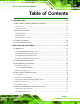
AFL-4 Series-N270 User Manual Quantity Item 1 AFL-4 Series-N270-R21 1 Power adapter 1 Power cord 1 Screw kit 4 Adhesive foam tape strips 1 User manual CD and driver CD Page 38 1 Touch pen 1 Remote control Image
AFL-4 Series-N270 User Manual Optional AFL-408A Faceplate: AFLFP-408A-W-R10(White) AFLFP-408A-B-R10 (Black) AFLFP-408A-G-R10 (Gray) AFL-408B Faceplate: AFLFP-408B-W-R10(White) AFLFP-408B-B-R10 (Black) AFLFP-408B-G-R10 (Gray) AFL-W410A Faceplate: AFLFP- W410A -W-R10(White) AFLFP- W410A -B-R10 (Black) AFLFP- W410A -G-R10 (Gray) AFL-412A Faceplate: AFLFP-412A-W-R10(White) AFLFP-412A-B-R10 (Black) AFLFP-412A-G-R10 (Gray) AFL-415A/AE Faceplate: AFLFP-415A-W-R10(White) AFLFP-415A-B-R10 (Black) AFLFP-415A-G-R10 (G
AFL-4 Series-N270 User Manual Stand (P/N:STAND-A08) for AFL-408A (P/N:STAND-A12) for AFL-412A Stand (P/N:STAND-100-RS) Stand (P/N: STAND-A-19) (P/N: STAND-B-19) (P/N: STAND-210-R11) Arm (P/N: ARM-11-RS) Arm (P/N: ARM-31-RS) 60 W DC/DC 9-30 VDC input vehicle power adapter: IDD-930160-KIT DC 12 V Input UPS AUPS-A10-R10 DC 12 V Input UPS AUPS-B10-R10 Page 40
AFL-4 Series-N270 User Manual DC 9-36V Input UPS AUPS-A20-R10 DC 9-36V Input UPS AUPS-B20-R10 Page 41
AFL-4 Series-N270 User Manual Chapter 4 4 Installation Page 42
AFL-4 Series-N270 User Manual 4.1 Anti-static Precautions WARNING: Failure to take ESD precautions during the maintenance of the AFL-4 Series-N270 may result in permanent damage to the AFL-4 Series-N270 and severe injury to the user. Electrostatic discharge (ESD) can cause serious damage to electronic components, including the AFL-4 Series-N270. Dry climates are especially susceptible to ESD.
AFL-4 Series-N270 User Manual Anti-static Discharge: If a user open the rear panel of the flat panel PC, to configure the jumpers or plug in added peripheral devices, ground themselves first and wear and anti-static wristband. 4.3 Preinstalled Components The following components are all preinstalled. Motherboard TFT LCD screen 1.
AFL-4 Series-N270 User Manual 4.5 Removing the Rear Panel To access the AFL-4 Series-N270 internally the rear panel must be removed. To remove the rear panel, please follow the steps below. Step 1: Place the AFL-4 Series-N270 face down on a flat surface. Step 2: Remove the retention screws (Figure 4-1). Figure 4-1: Back Cover Retention Screws Step 3: Lift the cover off and pull down the cover a bit to make it possible to lift the cover further more after removing the retention screws.
AFL-4 Series-N270 User Manual Step 1: Locate the CF slot cover. Remove the retention screw and cover (Figure 4-2). Figure 4-2: CF card slot location Step 2: Insert a CF card into the slot (Figure 4-3). Figure 4-3: CF Card Location Step 3: Replace the CF card slot cover. Step 4: Reinsert the retention screw.
AFL-4 Series-N270 User Manual 4.7 HDD Installation (AFL-412A and AFL-415A/AE Only) To install the HDD into the AFL-412A/AFL-415A/AE, please follow the steps below: Step 1: Remove the aluminum cover. Step 2: Remove the four HDD bracket retention screws and lift the HDD bracket off the panel PC. Step 3: Attach the HDD brackets to the HDD. To do this, align the four retention screw holes in the both sides of the HDD bracket with the retention screw holes on the sides of the HDD.
AFL-4 Series-N270 User Manual Step 1: Locate the AT/ATX switch on the bottom panel (Figureٛ 2-6). Step 2: Adjust the AT/ATX switch. Step 0: 4.8.1 AT Power Mode When AT mode is selected, power is controlled by a central power unit rather than a power switch. The AFL-4 Series-N270 panel PC turns on automatically when the power is connected.
AFL-4 Series-N270 User Manual 4.9 Jumper Settings NOTE: A jumper is a metal bridge used to close an electrical circuit. It consists of two or three metal pins and a small metal clip (often protected by a plastic cover) that slides over the pins to connect them. To CLOSE/SHORT a jumper means connecting the pins of the jumper with the plastic clip and to OPEN a jumper means removing the plastic clip from a jumper. The following jumpers can be found on the motherboard installed in the AFL-4 Series-N270.
AFL-4 Series-N270 User Manual 4.9.1 Access the Jumpers To access the jumpers, remove the back panel. To remove the back panel, please refer to Section 4.5. 4.9.2 ATX/AT Power Mode Jumper Jumper Label: JP4 Jumper Type: 2-pin header Jumper Settings: See Table 4-3 Jumper Location: See Figure 4-5 The ATX/AT Power Select jumper specifies the systems power mode as AT or ATX.
AFL-4 Series-N270 User Manual 4.9.3 Clear CMOS Jumper Jumper Label: J_CMOS1 Jumper Type: 3-pin header Jumper Settings: See Table 4-3 Jumper Location: See Figure 4-6 If the AFL-4 Series-N270 fails to boot due to improper BIOS settings, the clear CMOS jumper clears the CMOS data and resets the system BIOS information. To do this, use the jumper cap to close the pins for a few seconds then remove the jumper clip.
AFL-4 Series-N270 User Manual Figure 4-6: Clear CMOS Jumper 4.9.4 COM3 RX Function Select Jumper Jumper Label: JP6 Jumper Type: 12-pin header Jumper Settings: See Table 4-4 Jumper Location: See Figure 4-7 The COM3 RX Function Select jumper sets the communication protocol used by the COM3 port as RS-232, RS-422 or RS-485. The COM3 RX Function Select jumper settings are shown in the table below.
AFL-4 Series-N270 User Manual The COM3 RX Function Select jumper location is shown in Figure 4-7. Figure 4-7: COM3 RX Function Select Jumper Location 4.9.5 COM2 RS-232/422/485 Serial Port Select Jumper Jumper Label: JP9 Jumper Type: 8-pin header Jumper Settings: See Table 4-5 Jumper Location: See Figure 4-8 The COM2 RS-232/422/485 Serial Port Select jumper sets the communication protocol used by the second serial communications port (COM2) as RS-232, RS-422 or RS-485.
AFL-4 Series-N270 User Manual Short 7-8 RS-485 Table 4-5: COM2 RS-232/422/485 Serial Port Select Jumper Settings The COM2 RS-232/422/485 Serial Port Select jumper location is shown in Figure 4-8. Figure 4-8: COM2 RS-232/422/485 Serial Port Select Jumper Location 4.9.6 LCD Backlight Select Jumper Jumper Label: J_BL1 Jumper Type: 3-pin header Jumper Settings: See Table 4-5 Jumper Location: See Figure 4-8 The backlight inverter connector provides power to an LCD panel.
AFL-4 Series-N270 User Manual Table 4-6: LCD Backlight Select Jumper Settings The LCD Backlight Select jumper location is shown in Figure 4-8. Figure 4-9: LCD Backlight Select Jumper Location 4.9.7 LCD Power Select 1 Jumper Jumper Label: J_VLVDS1 Jumper Type: 3-pin header Jumper Settings: See Table 4-5 Jumper Location: See Figure 4-8 The LCD Power Select jumper sets the power setting of the LCD panel. Setting Description Short 1-2 +3.
AFL-4 Series-N270 User Manual The LCD Power Select jumper location is shown in Figure 4-8. Figure 4-10: LCD Power Select Jumper Location 4.9.8 LCD Panel Type Jumper Jumper Label: JP14 Jumper Type: 2-pin header Jumper Settings: See Table 4-5 Jumper Location: See Figure 4-8 The LCD Panel Type jumper sets the panel type. Setting Description Open LED Panel Closed LCD Panel Table 4-8: LCD Panel Type Jumper Settings The LCD Panel Type jumper location is shown in Figure 4-8.
AFL-4 Series-N270 User Manual Figure 4-11: LCD Panel Type Jumper Location 4.9.9 MCU LCD Panel Select Jumper Jumper Label: JP13 Jumper Type: 3-pin header Jumper Settings: See Table 4-5 Jumper Location: See Figure 4-8 The MCU LCD Panel Type jumper sets the MCU LCD panel power setting. Setting Description Short 1-2 +5V Short 2-3 +3.3V Table 4-9: MCU LCD Panel Select Jumper Settings The MCU LCD Panel Select jumper location is shown in Figure 4-8.
AFL-4 Series-N270 User Manual Figure 4-12: MCU LCD Panel Select Jumper Location 4.9.10 MCU LCD Type Select Jumper Jumper Label: JP17 Jumper Type: 2-pin header Jumper Settings: See Table 4-5 Jumper Location: See Figure 4-8 The MCU LCD Type Select jumper sets the MCU LCD type setting. Setting Description Open LCD Panel Closed LED Panel Table 4-10: MCU LCD Type Jumper Settings The MCU LCD Type jumper location is shown in Figure 4-8.
AFL-4 Series-N270 User Manual Figure 4-13: MCU LCD Type Jumper Location 4.9.11 Touch Screen Select Jumper Label: J1 Jumper Type: 4-pin header Jumper Settings: See Table 4-5 Jumper Location: See Figure 4-8 The Touch Screen Select jumper sets the touch screen as resistive 4 or 5 wire. Setting Description Short 1-2 5W Short 3-4 4W Table 4-11: Touch Screen Select Jumper Settings The Touch Screen Select jumper location is shown in Figure 4-8.
AFL-4 Series-N270 User Manual Figure 4-14: Touch Screen Select Jumper Location 4.10 Mounting the System WARNING! When mounting the flat panel PC onto an arm, onto the wall or into a wall, it is better to have more than one person to help with the installation to make sure the panel PC does not fall down and get damaged. The methods of mounting the AFL-4 Series-N270 are listed below. Wall mounting Arm mounting Rack mounting The mounting methods are described in the following sections.
AFL-4 Series-N270 User Manual 4.10.1 Wall Surface Mounting To mount the flat panel PC onto the wall, please follow the steps below. Step 1: Select the location on the wall for the wall-mounting bracket. Step 2: Carefully mark the locations of the four screw holes in the bracket on the wall. Step 3: Drill four pilot holes at the marked locations on the wall for the bracket retention screws. Step 4: Align the wall-mounting bracket screw holes with the pilot holes.
AFL-4 Series-N270 User Manual Ensure that all four of the mounting screws fit snuggly into their respective slotted holes. NOTE: In the diagram below the bracket is already installed on the wall. Figure 4-16: Chassis Support Screws Step 9: Secure the panel PC by fastening the retention screw of the wall-mounting bracket. (Figure 4-17).
AFL-4 Series-N270 User Manual Figure 4-17: Secure the Panel PC 4.10.2 In-wall Mounting Before installing into a wall mounting, attach the foam adhesive strips to the sides as shown below: Step 1: Place the AFL-4 Series-N270 face down on a flat surface. Figure 4-18: Cut Foam Tape Step 2: Cut the adhesive foam tape as shown above.
AFL-4 Series-N270 User Manual Figure 4-19: Attach Foam Tape Step 3: Attach the adhesive foam tape to the edge of rear panel of the AFL-4 Series-N270 (see Figure 4-19). Make sure the adhesive tape does not cover the screw holes as shown below. Step 0: Figure 4-20: Foam Tape Installed To mount the AFL-4 Series-N270 panel PC into a wall, please follow the steps below. Step 1: Select the position on the wall to mount the flat panel PC.
AFL-4 Series-N270 User Manual Figure 4-21: AFL-408A/B-N270 In-wall Panel Opening Figure 4-22: AFL-W410A-N270 In-wall Opening Page 65
AFL-4 Series-N270 User Manual Figure 4-23: AFL-412A-N270 In-wall Opening Figure 4-24: AFL-415A/AE-N270 In-wall Opening Step 3: Slide the flat panel PC through the hole until the frame is flush against the wall. Step 4: Tighten the screws that pass through the wall mounting screw holes in the AFL-4 Series-N270 until the screws are firmly secured to the wall (Figure 4-25).
AFL-4 Series-N270 User Manual Figure 4-25: Tighten the In-wall Mounting Screws 4.10.3 Arm Mounting The AFL-4 Series-N270 is VESA (Video Electronics Standards Association) compliant and can be mounted on an arm with a 75mm or 100mm interface pad. To mount the AFL-4 Series-N270 on an arm, please follow the steps below. Step 1: The arm is a separately purchased item. Please correctly mount the arm onto the surface it uses as a base.
AFL-4 Series-N270 User Manual Step 3: Align the retention screw holes on the mounting arm interface with those in the flat panel PC. The arm mount retention screw holes are shown in Figure 4-26. Figure 4-26: AFL-412A-N270 Arm Mounting Retention Screw Holes Step 4: Secure the flat panel PC to the interface pad by inserting four retention screws through the bottom of the mounting arm interface pad and into the flat panel PC. Step 0: 4.11 Bottom Panel Connectors 4.11.
AFL-4 Series-N270 User Manual Step 2: Align the connector. Align the RJ-45 connector on the LAN cable with one of the RJ-45 connectors on the bottom panel of the AFL-4 Series-N270. See Figure 4-27. Figure 4-27: LAN Connection Step 3: Insert the LAN cable RJ-45 connector. Once aligned, gently insert the LAN cable RJ-45 connector into the onboard RJ-45 connector. Step 0: 4.11.
AFL-4 Series-N270 User Manual Figure 4-28: Serial Device Connector Step 3: Insert the connector. Once aligned, gently insert the LAN cable RJ-45 connector into the onboard RJ-45 connector. Step 0: 4.11.2.1 RJ-45 Serial Port Pinouts The pinouts for RS-232, RS-422 and RS-485 communication are shown below. The COM1 serial port is RS-232 only. PIN NO.
AFL-4 Series-N270 User Manual 4.11.3 USB Device Connection There are four external USB 2.0 connectors. All connectors are perpendicular to the AFL-4 Series-N270. To connect a USB 2.0 or USB 1.1 device, please follow the instructions below. Step 1: Locate the USB connectors. The locations of the USB connectors are shown in Chapter 2. Step 2: Align the connectors. Align the USB device connector with one of the connectors on the bottom panel. See Figure 4-29.
AFL-4 Series-N270 User Manual Step 1: Install the faceplate by snapping the faceplate onto the AFL-4 Series-N270 frame. See Figure 4-30.
AFL-4 Series-N270 User Manual Chapter 5 5 System Maintenance Page 73
AFL-4 Series-N270 User Manual 5.1 System Maintenance Introduction If the components of the AFL-4 Series-N270 fail they must be replaced. Components that can be replaced include: CF Module Bluetooth module Wireless LAN module SO-DIMM module Please contact the system reseller or vendor to purchase the replacement parts. Back cover removal instructions for the AFL-4 Series-N270 are described below. 5.
AFL-4 Series-N270 User Manual Only handle the edges of the PCB: - When handling the PCB, hold the PCB by the edges. 5.3 Turn off the Power WARNING: Failing to turn off the system before opening it can cause permanent damage to the system and serious or fatal injury to the user. Before any maintenance procedures are carried out on the system, make sure the system is turned off. 5.4 Opening the System 5.4.
AFL-4 Series-N270 User Manual Figure 5-1: Back Cover Retention Screws Step 5: Lift the cover off and pull down the cover a bit to make it possible to lift the cover further more after removing the retention screws. More strength is required to separate the cover from the chassis. Step 0: 5.5 Replacing Components 5.5.1 Memory Module Replacement The flat panel PC is preinstalled with a 1 GB DDR2 memory module. If the memory module fails, follow the instructions below to replace it.
AFL-4 Series-N270 User Manual Figure 5-2: AFL-412A-N270 SO-DIMM Socket Location Step 3: Remove the DDR memory module by pulling both the spring retainer clips outward from the socket. Step 4: Grasp the DDR memory module by the edges and carefully pull it out of the socket. Step 5: Install the new DDR memory module by pushing it into the socket at an angle (Figure 5-3). Step 6: Gently pull the spring retainer clips of the SO-DIMM socket out and push the rear of the DDR memory module down (Figure 5-3).
AFL-4 Series-N270 User Manual Figure 5-3: DDR SO-DIMM Module Installation 5.5.2 CF Card Replacement The AFL-4 Series-N270 has one CF Type II slot. Follow the instructions below to replace the CF card. Step 1: Follow all anti-static procedures. See Section 5.2. Step 2: Turn off the power. See Section 5.3. Step 3: Follow the instruction listed in Section 4.6 to replace the CF card. Step 0: 5.6 Reinstalling the Covers WARNING: Failing to reinstall the covers may result in permanent damage to the system.
AFL-4 Series-N270 User Manual Chapter 6 6 BIOS Options Page 79
AFL-4 Series-N270 User Manual 6.1 Introduction A licensed copy of AMI BIOS is preprogrammed into the ROM BIOS. The BIOS setup program allows users to modify the basic system configuration. This chapter describes how to access the BIOS setup program and the configuration options that may be changed. 6.1.1 Starting Setup The AMI BIOS is activated when the computer is turned on. The setup program can be activated in one of two ways. 1. Press the DELETE key as soon as the system is turned on or 2.
AFL-4 Series-N270 User Manual F1 key General help, only for Status Page Setup Menu and Option Page Setup Menu F2 /F3 key Change color from total three colors. F2 to select color forward. F10 key Save all the CMOS changes, only for Main Menu Table 6-1: BIOS Navigation Keys 6.1.3 Getting Help When F1 is pressed a small help window describing the appropriate keys to use and the possible selections for the highlighted item appears. To exit the Help Window press ESC or the F1 key again. 6.1.
AFL-4 Series-N270 User Manual 6.2 Main The Main BIOS menu (BIOS Menu 1) appears when the BIOS Setup program is entered. 6 The Main menu gives an overview of the basic system information. Main Advanced PCIPNP BIOS SETUP UTILITY Boot Security Chipset System Overview AMIBIOS Version :08.00.15 Build Date :08/27/10 ID: :H571MR10 Exit Use [ENTER], [TAB] or [SHIFT-TAB] to select a field. Use [+] or [-] to configure system time. Processor Genuine Intel® CPU N270 @1.
AFL-4 Series-N270 User Manual The System Overview field also has two user configurable fields: System Time [xx:xx:xx] Use the System Time option to set the system time. Manually enter the hours, minutes and seconds. System Date [xx/xx/xx] Use the System Date option to set the system date. Manually enter the day, month and year. 6.
AFL-4 Series-N270 User Manual Main Advanced PCIPNP BIOS SETUP UTILITY Boot Security Chipset Advanced Settings WARNING: Setting wrong values in below sections may cause system to malfunction > > > > > > > Exit Configure CPU.
AFL-4 Series-N270 User Manual Frequency: Lists the CPU processing speed FSB Speed: Lists the FSB speed Cache L1: Lists the CPU L1 cache size Cache L2: Lists the CPU L2 cache size Ratio Actual Value: Lists the ratio actual value of the mainboard. 6.3.2 IDE Configuration Use the IDE Configuration menu (BIOS Menu 4) to change and/or set the configuration 6 of the IDE devices installed in the system.
AFL-4 Series-N270 User Manual Enhanced mode. In this mode, IDE channels and SATA channels are separated. This mode supports up to 6 storage devices. Some legacy OS do not support this mode. Legacy IDE Channels [SATA Pri, PATA Sec] SATA Only SATA Pri, PATA Sec Only the SATA drives are enabled. DEFAULT The IDE drives are enabled on the Primary IDE channel. The SATA drives are enabled on the Secondary IDE channel. The IDE drives are enabled on the primary PATA Only and secondary IDE channels.
AFL-4 Series-N270 User Manual Main Advanced PCIPNP BIOS SETUP UTILITY Boot Security Chipset Primary IDE Master Device :Not Detected Type LBA/Large Mode Block (Multi-Sector Transfer) PIO Mode DMA Mode S.M.A.R.T. 32Bit Data Transfer [Auto] [Auto] [Auto] [Auto] [Auto] [Auto] [Enabled] Exit Select the type of device connected to the system + F1 F10 ESC Select Screen Select Item Change Option General Help Save and Exit Exit v02.
AFL-4 Series-N270 User Manual Not Installed BIOS is prevented from searching for an IDE disk drive on the specified channel. Auto DEFAULT The BIOS auto detects the IDE disk drive type attached to the specified channel. This setting should be used if an IDE hard disk drive is attached to the specified channel. CD/DVD The CD/DVD option specifies that an IDE CD-ROM drive is attached to the specified IDE channel.
AFL-4 Series-N270 User Manual Auto DEFAULT BIOS auto detects Multi-Sector Transfer support on the drive on the specified channel. If supported the data transfer to and from the device occurs multiple sectors at a time. PIO Mode [Auto] Use the PIO Mode option to select the IDE PIO (Programmable I/O) mode program timing cycles between the IDE drive and the programmable IDE controller. As the PIO mode increases, the cycle time decreases. Auto DEFAULT BIOS auto detects the PIO mode.
AFL-4 Series-N270 User Manual Auto BIOS auto detects HDD SMART support. DEFAULT Disabled Prevents BIOS from using the HDD SMART feature. Allows BIOS to use the HDD SMART feature Enabled 32Bit Data Transfer [Enabled] Use the 32Bit Data Transfer BIOS option to enables or disable 32-bit data transfers. Disabled Enabled Prevents the BIOS from using 32-bit data transfers. DEFAULT Allows BIOS to use 32-bit data transfers on supported hard disk drives. 6.3.
AFL-4 Series-N270 User Manual 3F8/IRQ4 DEFAULT Serial Port 1 I/O port address is 3F8 and the interrupt address is IRQ4 2F8/IRQ3 Serial Port 1 I/O port address is 2F8 and the interrupt address is IRQ3 3E8/IRQ4 Serial Port 1 I/O port address is 3E8 and the interrupt address is IRQ4 2E8/IRQ3 Serial Port 1 I/O port address is 2E8 and the interrupt address is IRQ3 Serial Port3 Address [3E8] Use the Serial Port3 Address option to select the Serial Port 3 base address.
AFL-4 Series-N270 User Manual Main Advanced PCIPNP BIOS SETUP UTILITY Boot Security Chipset Exit Hardware Health Configuration CPU Temperature :47ºC/116ºF System Temperature :47ºC/116ºF CPU Core +1.05V +3.30V +5.00V +12.0V +1.5V +1.8V 5VSB VBAT :1.184 V :1.040 V :3.328 V :4.999 V :11.904 V :1.472 V :1.808 V :4.999 V :3.280 V Select Screen Select Item F1 General Help F10 Save and Exit ESC Exit v02.61 ©Copyright 1985-2006, American Megatrends, Inc.
AFL-4 Series-N270 User Manual 6.3.5 Power Configuration The Power Configuration menu (BIOS Menu 8) configures the Advanced Configuration and Power Interface (ACPI) and Power Management (APM) options. Main Advanced PCIPNP BIOS SETUP UTILITY Boot Security Chipset Current Jumper Setting [ATX] > ACPI Configuration > APM Configuration Exit Section for Advanced ACPI Configuration.
AFL-4 Series-N270 User Manual Main Advanced PCIPNP BIOS SETUP UTILITY Boot Security Chipset ACPI Settings Suspend mode [S1 (POS)] Exit Select the ACPI state used for System Suspend. Select Screen Select Item + Change Option F1 General Help F10 Save and Exit ESC Exit v02.61 ©Copyright 1985-2006, American Megatrends, Inc.
AFL-4 Series-N270 User Manual Main Advanced PCIPNP BIOS SETUP UTILITY Boot Security Chipset APM Configuration Restore on AC Power Loss [Last State] Power Button Mode [On/Off] Advanced Resume Resume Resume Resume Event Controls on Ring on PCI-Express WAKE# on RTC Alarm Exit If the AT/ATX jumper has been set to AT mode, this item will be changed to “power on” automatically.
AFL-4 Series-N270 User Manual Resume on Ring [Disabled] Use the Resume on Ring BIOS option to enable activity on the RI (ring in) modem line to rouse the system from a suspend or standby state. That is, the system will be roused by an incoming call on a modem.
AFL-4 Series-N270 User Manual 6.3.6 Remote Access Configuration Use the Remote Access Configuration menu (BIOS Menu 11) to configure remote access parameters. The Remote Access Configuration is an AMIBIOS feature and allows a remote host running a terminal program to display and configure the BIOS settings. Main Advanced PCIPNP BIOS SETUP UTILITY Boot Security Chipset Configure Remote Access type and parameters Remote Access [Disabled] Exit Select Remote Access type.
AFL-4 Series-N270 User Manual These configuration options are discussed below. Serial Port Number [COM1] Use the Serial Port Number option to select the serial port used for remote access. COM1 COM3 DEFAULT System is remotely accessed through COM1 System is remotely accessed through COM3 NOTE: Make sure the selected COM port is enabled through the Super I/O configuration menu.
AFL-4 Series-N270 User Manual Disabled The console is not redirected after POST Boot Loader Redirection is active during POST and during Boot Loader Always DEFAULT Redirection is always active (Some OSes may not work if set to Always) Terminal Type [ANSI] Use the Terminal Type BIOS option to specify the remote terminal type. ANSI VT100 The target terminal type is VT100 VT-UTF8 The target terminal type is VT-UTF8 DEFAULT The target terminal type is ANSI 6.3.
AFL-4 Series-N270 User Manual USB Functions [Enabled] Use the USB Function option to enable or disable the USB controllers. Disabled Enabled USB controllers are enabled DEFAULT USB controllers are disabled USB 2.0 Controller [Enabled] The USB 2.0 Controller BIOS option enables or disables the USB 2.
AFL-4 Series-N270 User Manual HiSpeed DEFAULT The controller is capable of operating at high speed 480 Mb/s 6.4 PCI/PnP Use the PCI/PnP menu (BIOS Menu 13) to configure advanced PCI and PnP settings. 6 WARNING: Setting wrong values for the BIOS selections in the PCIPnP BIOS menu may cause the system to malfunction.
AFL-4 Series-N270 User Manual Available DEFAULT The specified IRQ is available to be used by PCI/PnP devices Reserved The specified IRQ is reserved for use by Legacy ISA devices Available IRQ addresses are: IRQ3 IRQ4 IRQ5 IRQ7 IRQ9 IRQ10 IRQ11 IRQ14 IRQ15 DMA Channel# [Available] Use the DMA Channel# option to assign a specific DMA channel to a particular PCI/PnP device.
AFL-4 Series-N270 User Manual Reserved Memory Size [Disabled] Use the Reserved Memory Size BIOS option to specify the amount of memory that should be reserved for legacy ISA devices. Disabled 16K 16KB reserved for legacy ISA devices 32K 32KB reserved for legacy ISA devices 64K 64KB reserved for legacy ISA devices DEFAULT No memory block reserved for legacy ISA devices 6.5 Boot Use the Boot menu (BIOS Menu 14) to configure system boot options.
AFL-4 Series-N270 User Manual Main Advanced PCIPNP BIOS SETUP UTILITY Boot Security Chipset Boot Settings Configuration Quick Boot [Enabled] Quiet Boot [Enabled] AddOn ROM Display Mode [Force BIOS] Bootup Num-Lock [On] Boot from LAN Support [Disabled] Spread Spectrum Function [Disabled] Exit Allows BIOS to skip certain tests while booting. This will decrease the time needed to boot the system.
AFL-4 Series-N270 User Manual Keep Current Allows the computer system to display the information during system boot. Bootup Num-Lock [On] The Bootup Num-Lock BIOS option allows the Number Lock setting to be modified during boot up. Off Does not enable the keyboard Number Lock automatically. To use the 10-keys on the keyboard, press the Number Lock key located on the upper left-hand corner of the 10-key pad. The Number Lock LED on the keyboard lights up when the Number Lock is engaged.
AFL-4 Series-N270 User Manual 6.5.2 Boot Device Priority Use the Boot Device Priority menu (BIOS Menu 16) to specify the boot sequence from the available devices. The drive sequence also depends on the boot sequence in the individual device section. Main Advanced PCIPNP BIOS SETUP UTILITY Boot Security Chipset Boot Device Priority 1st Boot Device [HDD:SS-iEi Global] Exit Specifies the boot sequence from the available devices.
AFL-4 Series-N270 User Manual 6.5.3 Hard Disk Drives Use the Hard Disk Drives menu (BIOS Menu 17) to specify the boot sequence of the available HDDs. Only installed hard drives are shown. Main Advanced PCIPNP BIOS SETUP UTILITY Boot Security Chipset Hard Disk Drives > 1st Drive [HDD:SS-iEi Global] Exit Specifies the boot sequence from the available devices. + F1 F10 ESC Select Screen Select Item Change Option General Help Save and Exit Exit v02.
AFL-4 Series-N270 User Manual Change Supervisor Password Use the Change Supervisor Password to set or change a supervisor password. The default for this option is Not Installed. If a supervisor password must be installed, select this field and enter the password. After the password has been added, Install appears next to Change Supervisor Password. Change User Password Use the Change User Password to set or change a user password. The default for this option is Not Installed.
AFL-4 Series-N270 User Manual Main Advanced PCIPNP BIOS SETUP UTILITY Boot Security Chipset Advanced Chipset Settings WARNING: Setting wrong values in below section may cause system to malfunction. Exit Configure North Bridge features. > North Bridge Configuration > South Bridge Configuration Select Screen Select Item Enter Go to SubScreen F1 General Help F10 Save and Exit ESC Exit v02.61 ©Copyright 1985-2006, American Megatrends, Inc.
AFL-4 Series-N270 User Manual Main Advanced PCIPNP BIOS SETUP UTILITY Boot Security Chipset North Bridge Chipset Configuration Memory Hole [Disabled] Internal Graphics Mode Select [Enabled, 8MB] Exit Options: Disabled 15MB-16MB Video Function Configuration DVMT Mode Select [DVMT Mode] DVMT/FIXED Memory [128MB] Boot Display Device LFP Panel Type LFP Current Jumper Setting [Auto] [by H/W] [800x600 18b] Select Screen Select Item
AFL-4 Series-N270 User Manual Enable, 8MB DEFAULT 8MB of memory used by internal graphics device DVMT Mode Select [DVMT Mode] Use the DVMT Mode Select option to select the Intel Dynamic Video Memory Technology (DVMT) operating mode. A fixed portion of graphics memory is reserved as Fixed Mode graphics memory. DVMT Mode DEFAULT Graphics memory is dynamically allocated according to the system and graphics needs.
AFL-4 Series-N270 User Manual LFP Panel Type [by H/W] Use the LFP Panel Type option to select the type of flat panel connected to the system. Configuration options are listed below. 640x480 18b 800x480 18b 800x600 18b 1024x768 18b 1280x1024 36b 1024x600 18b 1440x900 36b 1600x1200 36b by H/W DEFAULT 6.7.2 Southbridge Configuration The Southbridge Configuration menu (BIOS Menu 21) allows the Southbridge chipset 6 to be configured.
AFL-4 Series-N270 User Manual Audio Controller [Auto] The Audio Controller option enables or disables the audio controller. The audio controller is automatically detected Auto and enabled All Disabled DEFAULT The on-board audio controller is disabled. 6.8 Exit Use the Exit menu (BIOS Menu 22) to load default BIOS values, optimal failsafe values 6 and to save configuration changes.
AFL-4 Series-N270 User Manual Discard Changes Use the Discard Changes option to discard the changes and remain in the BIOS configuration setup program. Load Optimal Defaults Use the Load Optimal Defaults option to load the optimal default values for each of the parameters on the Setup menus. F9 key can be used for this operation. Load Failsafe Defaults Use the Load Failsafe Defaults option to load failsafe default values for each of the parameters on the Setup menus.
AFL-4 Series-N270 User Manual Chapter 7 7 Software Drivers Page 115
AFL-4 Series-N270 User Manual 7.1 Available Software Drivers NOTE: The content of the CD may vary throughout the life cycle of the product and is subject to change without prior notice. Visit the IEI website or contact technical support for the latest updates. The following drivers can be installed on the system: Chipset VGA Audio LAN Touch screen Bluetooth Wireless KeypadAP PC Camera Installation instructions are given below. 7.
AFL-4 Series-N270 User Manual Figure 7-1: Start Up Screen Step 3: Select the AFL-4 Series-N270 model. Step 4: The list of drivers in Figure 7-2 appears.
AFL-4 Series-N270 User Manual 7.3 Chipset Driver Installation To install the chipset driver, please do the following. Step 1: Access the driver list shown in Figure 7-2. (See Section 7.2) Step 2: Click “NB” and double click “Setup.exe”. Step 3: The setup files are extracted as shown in Figure 7-3. Figure 7-3: Chipset Driver Screen Step 4: When the setup files are completely extracted the Welcome Screen in Figure 7-4 appears.
AFL-4 Series-N270 User Manual Figure 7-4: Chipset Driver Welcome Screen Step 5: Click NEXT to continue. Step 6: The license agreement in Figure 7-5 appears. Figure 7-5: Chipset Driver License Agreement Step 7: Read the License Agreement. Step 8: Click the YES button to accept the license agreement and continue.
AFL-4 Series-N270 User Manual Step 9: The Read Me file in Figure 7-6 appears. Figure 7-6: Chipset Driver Read Me File Step 10: Click NEXT to continue. Step 11: Setup Operations are performed as shown in Figure 7-7. Figure 7-7: Chipset Driver Setup Operations Step 12: Once the Setup Operations are complete, click the NEXT icon to continue.
AFL-4 Series-N270 User Manual Step 13: The Finish screen appears. Figure 7-8: Chipset Driver Installation Finish Screen Select “Yes, I want to restart the computer now” and click the Finish icon. See Figure 7-9.
AFL-4 Series-N270 User Manual 7.4 VGA Driver Installation To install the VGA driver, please do the following. Step 1: Access the driver list shown in Figure 7-2. (See Section 7.2) Step 2: Click “VGA” and double click the “Setup.exe” file. Step 3: The VGA Read Me file in Figure 7-10 appears. Figure 7-10: VGA Driver Read Me File Step 4: Click NEXT to continue. Step 5: The installation files are extracted. See Figure 7-11.
AFL-4 Series-N270 User Manual Figure 7-11: VGA Driver Setup Files Extracted Step 6: The Welcome Screen in Figure 7-12 appears. Figure 7-12: VGA Driver Welcome Screen Step 7: Click NEXT to continue. Step 8: The license agreement in Figure 7-13 appears.
AFL-4 Series-N270 User Manual Figure 7-13: VGA Driver License Agreement Step 9: Read the License Agreement. Step 10: Click YES to accept the license agreement and continue. Step 11: The Readme file in Figure 7-14 appears. Figure 7-14: VGA Driver Read Me File Step 12: Click NEXT to continue.
AFL-4 Series-N270 User Manual Step 13: Setup Operations are performed as shown in Figure 7-15. NOTE: The “Found New Hardware Wizard” will appear and then disappear during this step. Do not adjust any settings in the “Found New Hardware Wizard” window. Figure 7-15: VGA Driver Setup Operations Step 14: Once the Setup Operations are complete, click NEXT to continue. Step 15: The Finish screen appears.
AFL-4 Series-N270 User Manual Figure 7-16: VGA Driver Installation Finish Screen Step 16: Select “Yes, I want to restart the computer now” and click FINISH . See Figure 7-16.Step 0: 7.5 Realtek HD Audio Driver (ALC883) Installation To install the Realtek High Definition (HD) Audio driver, please follow the steps below. 7.5.1 BIOS Setup Step 1: Enter the BIOS setup. To do this, reboot the system and press DEL during POST. Step 2: Go to the Southbridge Configuration menu.
AFL-4 Series-N270 User Manual Figure 7-17: Locate the Setup Program Icon Step 3: The InstallShield Wizard is prepared to guide the user through the rest of the process (Figure 7-18). Figure 7-18: Preparing Setup Screen Step 4: Once initialized, the InstallShield Wizard welcome screen appears (Figure 7-19).
AFL-4 Series-N270 User Manual Figure 7-19: InstallShield Wizard Welcome Screen Step 5: Click NEXT to continue the installation. Step 6: InstallShield starts to install the new software as shown in Figure 7-20. Figure 7-20: Audio Driver Software Configuration Step 7: The Installation Wizard updates the system as shown in Figure 7-21.
AFL-4 Series-N270 User Manual Figure 7-21: Installation Wizard Updates the System Step 8: After the driver installation process is complete, a confirmation screen appears (Figure 7-22). Figure 7-22: Restart the Computer Step 9: The confirmation screen offers the option of restarting the computer now or later. For the settings to take effect, the computer must be restarted. Click FINISH to restart the computer.
AFL-4 Series-N270 User Manual 7.6 LAN Driver Installation To install the LAN driver, please do the following. Step 1: Access the driver list shown in Figure 7-2. (See Section 7.2) Step 2: Click “LAN” and locate the setup.exe. Double click the setup.exe file to start installing the LAN driver. Step 3: The Welcome screen in Figure 7-23 appears. Figure 7-23: LAN Driver Welcome Screen Step 4: Click Next to continue. Step 5: The Ready to Install screen in Figure 7-24 appears.
AFL-4 Series-N270 User Manual Figure 7-24: LAN Driver Welcome Screen Step 7: The program begins to install. Step 8: The installation progress can be monitored in the progress bar shown in Figure 7-25. Figure 7-25: LAN Driver Installation Step 9: When the driver installation is complete, the screen in Figure 7-26 appears.
AFL-4 Series-N270 User Manual Step 0: Figure 7-26: LAN Driver Installation Complete 7.7 Touch Screen Driver To install the touch panel software driver, please follow the steps below. Step 1: Access the driver list shown in Figure 7-2. (See Section 7.2) Step 2: Click “Touch Screen”. Double click the “Setup.exe” installation file. Step 3: A welcome screen appears (Figure 7-27). To continue the installation process click NEXT.
AFL-4 Series-N270 User Manual Figure 7-27: Welcome Screen Step 4: The license agreement shown in Figure 7-28 appears. Agree to the license by selecting “I accept the terms in the license agreement”. Figure 7-28: License Agreement Step 5: Click NEXT and the Installshield Wizard is ready to install the program (Figure 7-29).
AFL-4 Series-N270 User Manual Figure 7-29: Ready to Install the Program Step 6: Click INSTALL to continue. The Installing PenMount screen appears as the program is installed (Figure 7-30). Figure 7-30: Installing PenMount DMC9000 Step 7: The user is then prompted to select to restart the computer now or later (Figure 7-31). For the settings to take effect, the computer must be restarted. Click Yes to restart the computer.
AFL-4 Series-N270 User Manual Figure 7-31: Reboot the Computer 7.8 Bluetooth Driver To install the Bluetooth software driver, please follow the steps below. Step 1: Select Bluetooth from the list in Figure 7-2. Step 2: A new window opens (Figure 7-32). Click the Setup.exe to install the Bluetooth driver.
AFL-4 Series-N270 User Manual Step 3: A welcome screen appears (Figure 7-33). To continue the installation process click NEXT. Figure 7-33: Welcome Screen Step 4: The license agreement shown in Figure 7-34 appears. Agree to the license by selecting “I accept the terms in the license agreement”. Figure 7-34: License Agreement Step 5: The Custom Settings screen in Figure 7-35 appears next.
AFL-4 Series-N270 User Manual Figure 7-35: Bluetooth Driver Setup Options Step 6: Select the required installation configuration in Figure 7-35 and click NEXT to continue. Step 7: The Destination Folder screen in Figure 7-36 appears next. Confirm the destination folder to install the Bluetooth driver.
AFL-4 Series-N270 User Manual Step 8: Click NEXT and the Installshield Wizard is ready to install the program (Figure 7-37). Figure 7-37: Ready to Install the Program Step 9: Click INSTALL to continue. The Installing BlueSoleil screen appears as the program is installed (Figure 7-38). Figure 7-38: Installing BlueSoleil Step 10: When the installation process is complete, the Setup Complete screen appears. See Figure 7-39.
AFL-4 Series-N270 User Manual Figure 7-39: Bluetooth Driver Complete Installation Screen Step 11: To complete the chipset driver installation, click FINISH. The user is then prompted to select to restart the computer now or later (Figure 7-40). For the settings to take effect, the computer must be restarted. Click Yes to restart the computer. Step 0: Figure 7-40: Reboot the Computer 7.9 Wireless Driver To install the wireless driver, please follow the steps below.
AFL-4 Series-N270 User Manual . Figure 7-41: Wireless Driver Folder Step 3: The license agreement in Figure 7-42 appears. Figure 7-42: Wireless Driver License Agreement Step 4: Accept the conditions of the license agreement and click NEXT to continue. Step 5: The Configuration Tool Options screen in Figure 7-43 appears next.
AFL-4 Series-N270 User Manual Figure 7-43: Wireless Driver Configuration Tool Options Step 6: Select configuration tool in Figure 7-43 and click NEXT to continue. Step 7: The Wireless Mode Options window in Figure 7-44 appears. Figure 7-44: Wireless Mode Select Window Step 8: Click NEXT in Figure 7-44. Step 9: Click INSTALL in Figure 7-45 to start to install the driver.
AFL-4 Series-N270 User Manual Figure 7-45: Wireless Driver Installation Step 10: When the installation is finished. Click FINISH in the termination screen. Step 0: 7.10 KeypadAP Driver To install the KeypadAP software driver, please follow the steps below. Step 1: Select KEYPADAP from the list in Figure 7-2. Step 2: A new window opens (Figure 7-46). Double click the KeypadAP v1.5.msi to install the KeypadAP driver.
AFL-4 Series-N270 User Manual Figure 7-46: Bluetooth Driver Icon Step 3: A welcome screen appears (Figure 7-47). To continue the installation process click NEXT. Figure 7-47: Welcome Screen Step 4: Install wizard is ready to install the program (Figure 7-48). Click next to begin installation.
AFL-4 Series-N270 User Manual Figure 7-48: Ready to Install the Program Step 5: The Installing KeypadAP screen appears as the program is installed (Figure 7-49). Figure 7-49: Installing KeypadAP Step 6: When the installation process is complete, the Setup Complete screen appears. See Figure 7-50.
AFL-4 Series-N270 User Manual Figure 7-50: KeypadAP Driver Complete Installation Screen Step 7: To complete the driver installation, click Close. Step 0: 7.11 PC Camera To install the PC camera driver, please do the following. Step 1: Access the driver list shown in Figure 7-2. (See Section 7.2) Step 2: Click “WEBCOM” and double click the “Setup.exe” file. Step 3: The InstallShield Wizard is prepared to guide the user through the rest of the process (Figure 7-51).
AFL-4 Series-N270 User Manual Figure 7-51: Preparing Setup Screen Step 4: Once initialized, the InstallShield Wizard welcome screen appears (Figure 7-52). Figure 7-52: InstallShield Wizard Welcome Screen Step 5: Click NEXT to continue the installation. Step 6: The following Installation options screen appears as shown in Figure 7-53. Select the installation type and click continue.
AFL-4 Series-N270 User Manual Figure 7-53: Installation Selection Type Step 7: The following Ready to Install window appears in Figure 7-54. Click Install. Figure 7-54: Ready to Install Window Step 8: The Installation Wizard updates the system as shown in Figure 7-55.
AFL-4 Series-N270 User Manual Figure 7-55: Installation Wizard Updates the System Step 9: The follow screen may appear, click continue anyway. Figure 7-56: Software Installation Alert Step 10: After the driver installation process is complete, a confirmation screen appears (Figure 7-57).
AFL-4 Series-N270 User Manual Figure 7-57: Installation Complete Step 11: Click FINISH to complete installation.
AFL-4 Series-N270 User Manual Appendix A A Terminology Page 150
AFL-4 Series-N270 User Manual AC ’97 Audio Codec 97 (AC’97) refers to a codec standard developed by Intel® in 1997. ACPI Advanced Configuration and Power Interface (ACPI) is an OS-directed configuration, power management, and thermal management interface. AHCI Advanced Host Controller Interface (AHCI) is a SATA Host controller register-level interface. ATA The Advanced Technology Attachment (ATA) interface connects storage devices including hard disks and CD-ROM drives to a computer.
AFL-4 Series-N270 User Manual DIMM Dual Inline Memory Modules are a type of RAM that offer a 64-bit data bus and have separate electrical contacts on each side of the module. EIST Enhanced Intel® SpeedStep Technology (EIST) allows users to modify the power consumption levels and processor performance through application software. The application software changes the bus-to-core frequency ratio and the processor core voltage.
AFL-4 Series-N270 User Manual SATA Serial ATA (SATA) is a serial communications bus designed for data transfers between storage devices and the computer chipsets. The SATA bus has transfer speeds up to 1.5 Gbps and the SATA II bus has data transfer speeds of up to 3.0 Gbps. S.M.A.R.T Self Monitoring Analysis and Reporting Technology (S.M.A.R.T) refers to automatic status checking technology implemented on hard disk drives.
AFL-4 Series-N270 User Manual Appendix B B Watchdog Timer Page 154
AFL-4 Series-N270 User Manual NOTE: The following discussion applies to DOS environment. IEI support is contacted or the IEI website visited for specific drivers for more sophisticated operating systems, e.g., Windows and Linux. The Watchdog Timer is provided to ensure that standalone systems can always recover from catastrophic conditions that cause the CPU to crash. This condition may have occurred by external EMIs or a software bug.
AFL-4 Series-N270 User Manual NOTE: When exiting a program it is necessary to disable the Watchdog Timer, otherwise the system resets.
AFL-4 Series-N270 User Manual Appendix C C Compatibility Page 157
AFL-4 Series-N270 User Manual NOTE: The compatible items described here have been tested by the IEI R&D team and found to be compatible with the AFL-4 Series-N270 C.1 Compatible Operating Systems The following operating systems have been successfully run on the AFL-4 Series-N270. MS-DOS 6.22 Microsoft Windows XP (32-bit) Microsoft Windows 2000 Red Hat 9.0 C.
AFL-4 Series-N270 User Manual C.3 Compatible Memory Modules NOTE: The memory modules listed below have been tested on the AFL-4 Series-N270 other memory modules that comply with the specifications may also work on the AFL-4 Series-N270 but have not been tested. The following memory modules have been successfully tested on the AFL-4 Series-N270. Manufacturer Kingston Model No.
AFL-4 Series-N270 User Manual Appendix D D Digital I/O Interface Page 160
AFL-4 Series-N270 User Manual D.1 Introduction The DIO connector on the AFL-4 Series-N270 is interfaced to GPIO ports on the Super I/O chipset. The DIO has both 4-bit digital inputs and 4-bit digital outputs. The digital inputs and digital outputs are generally control signals that control the on/off circuit of external devices or TTL devices. Data can be read or written to the selected address to enable the DIO functions.
AFL-4 Series-N270 User Manual D.3 Assembly Language Samples D.3.1 Enable the DIO Input Function The BIOS interrupt call INT 15H controls the digital I/O. An assembly program to enable digital I/O input functions is listed below. MOV AX, 6F08H Sets the digital port as input INT 15H Initiates the INT 15H BIOS call D.3.2 Enable the DIO Output Function The BIOS interrupt call INT 15H controls the digital I/O. An assembly program to enable digital I/O output functions is listed below.
AFL-4 Series-N270 User Manual Appendix E E Hazardous Materials Disclosure Page 163
AFL-4 Series-N270 User Manual E.1 Hazardous Materials Disclosure Table for IPB Products Certified as RoHS Compliant Under 2002/95/EC Without Mercury The details provided in this appendix are to ensure that the product is compliant with the Peoples Republic of China (China) RoHS standards. The table below acknowledges the presences of small quantities of certain materials in the product, and is applicable to China RoHS only.
AFL-4 Series-N270 User Manual Part Name Toxic or Hazardous Substances and Elements Lead Mercury Cadmium Hexavalent Polybrominated Polybrominated (Pb) (Hg) (Cd) Chromium Biphenyls Diphenyl (CR(VI)) (PBB) Ethers (PBDE) Housing X O O O O X Display X O O O O X Printed Circuit X O O O O X X O O O O O X O O O O X Fan Assembly X O O O O X Power Supply X O O O O X O O O O O O Board Metal Fasteners Cable Assembly Assemblies Battery O: This toxic
AFL-4 Series-N270 User Manual 此附件旨在确保本产品符合中国 RoHS 标准。以下表格标示此产品中某有毒物质的含量符 合中国 RoHS 标准规定的限量要求。 本产品上会附有”环境友好使用期限”的标签,此期限是估算这些物质”不会有泄漏或突变”的 年限。本产品可能包含有较短的环境友好使用期限的可替换元件,像是电池或灯管,这些元 件将会单独标示出来。 部件名称 有毒有害物质或元素 铅 汞 镉 六价铬 多溴联苯 多溴二苯 (Pb) (Hg) (Cd) (CR(VI)) (PBB) 醚 (PBDE) 壳体 X O O O O X 显示 X O O O O X 印刷电路板 X O O O O X 金属螺帽 X O O O O O 电缆组装 X O O O O X 风扇组装 X O O O O X 电力供应组装 X O O O O X 电池 O O O O O O O: 表示该有毒有害物质在该部件所有物质材料中的含量均在 SJ/T11363-2006 标准规