
User guide

AFL-4 Series-N270 User Manual
Page 67
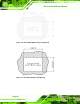
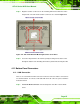
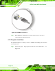
Figure 4-23: Serial Device Connector
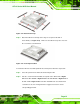
Step 3: Insert the connector. Once aligned, gently insert the LAN cable RJ-45
connector into the onboard RJ-45 connector.
Step 0:
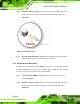
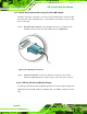
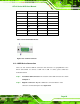
4.11.2.1 RJ-45 Serial Port Pinouts
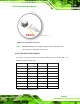
The pinouts for RS-232, RS-422 and RS-485 communication are shown below. The
COM1 serial port is RS-232 only.
PIN NO. RS-232 RS-422 RS-485
1 DCD TX- D-
2 DSR RX-
3 RX TX+ D+
4 RTS RX+
5 TX
6 CTS
7 DTR
8 RI
SHIELD GND
Table 4-7: RS-232/422/485 Pinouts