
Manual

AFL-08B-N270 User Manual
Page 46
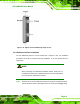
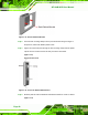
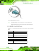
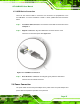
Figure 2-20: Serial Device Connector
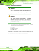
Step 3: Secure the connector. Secure the serial device connector to the external
interface by tightening the two retention screws on either side of the connector.
Step 0:
2.7.2.1 COM3 RS-422 and RS-485 Pinouts
The pinouts for RS-422 and RS-485 operation of external serial port COM3 are detailed
below.
COM 3 RS-422 Description
Pin 1 TX-
Pin 2 TX+
Pin 6 RX-
Pin 7 RX+
Table 2-9: RS-422 Pinouts
COM 3 RS-485 Description
Pin 1 Data-
Pin 2 Data+
Table 2-10: RS-485 Pinouts