
Manual

AFL-08B-N270 User Manual
Page 45
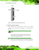
Step 1: Locate the RJ-45 connector on the bottom panel of the AFL-08B-N270 Series.
Step 2: Align the connector. Align the RJ-45 connector on the LAN cable with one of
the RJ-45 connectors on the bottom panel of the AFL-08B-N270. See Figure
2-19.
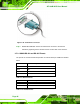
Figure 2-19: LAN Connection
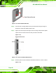
Step 3: Insert the LAN cable RJ-45 connector. Once aligned, gently insert the LAN
cable RJ-45 connector into the onboard RJ-45 connector. Step 0:
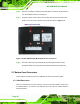
2.7.2 Serial Device Connection and RS-422/485 Pinouts
The AFL-08B-N270 has two DB-9 connectors for connecting to RS-232 and
RS-232/422/485 serial devices on the bottom panel. Follow the steps below to connect a
serial device to the panel PC. Please see Section 2.7.2.1 belo
w for the RS-422 and
RS-485 pinouts of Serial Port COM3.
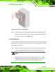
Step 1: Locate the DB-9 connector. The location of the DB-9 connector is shown in
Chapter 3.
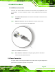
Step 2: Insert the serial connector. Insert the DB-9 connector of a serial device into
the DB-9 connector on the external peripheral interface. See Figure 2-20.