
User Manual


AFL-08AH-N270-CR Panel PC
Page XI
List of Figures
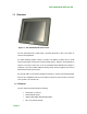
Figure 1-1: AFL-08AH-N270-CR Flat Panel PC ............................................................................2
Figure 1-2: AFL-08AH-N270-CR Front View.................................................................................4
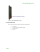
Figure 1-3: AFL-08AH-N270-CR Rear View ..................................................................................4
Figure 1-4: AFL-08AH-N270-CR I/O Interface Connector Panel.................................................5
Figure 1-5: AFL-08AH-N270-CR Top View....................................................................................5
Figure 1-6: AFL-08AH-N270-CR Side View...................................................................................6
Figure 2-1: AFL-08AH-N270-CR Dimensions (mm) ...................................................................10
Figure 2-2: Preinstalled DDR2 SO-DIMM....................................................................................12
Figure 2-3: RJ-45 Ethernet Connectors......................................................................................13
Figure 2-4: External USB Ports ...................................................................................................14
Figure 2-5: LCD Screen................................................................................................................14
Figure 2-6: Audio Jack.................................................................................................................15
Figure 2-7: Stereo Speakers........................................................................................................15
Figure 2-8: Power Connector ......................................................................................................16
Figure 2-9: PIFA Antenna and Wireless Module........................................................................17
Figure 4-1: Back Cover Retention Screws .................................................................................24
Figure 4-2: Aluminum Back Cover Retention Screws ..............................................................25
Figure 4-3: Wall-mounting Bracket.............................................................................................27
Figure 4-4: Chassis Support Screws..........................................................................................29
Figure 4-5: Secure the Panel PC .................................................................................................29
Figure 4-6: AFL-08AH-N270-CR Panel Opening ........................................................................30
Figure 4-7: Tighten the Panel Mounting Clamp Screws ...........................................................31
Figure 4-8: Arm Mounting Retention Screw Holes....................................................................32
Figure 4-9: The Rack/Cabinet Bracket........................................................................................33
Figure 4-10: Secure the Rack/Cabinet Bracket..........................................................................34
Figure 4-11: Install into a Rack/Cabinet .....................................................................................34
Figure 4-12: LAN Connection......................................................................................................35
Figure 4-13: USB Device Connection .........................................................................................37
Figure 5-1: Back Cover Retention Screws .................................................................................41
Figure 5-2: Aluminum Back Cover Retention Screws ..............................................................42
Figure 5-3: AFL-10A-N270 SO-DIMM Socket Location..............................................................42