
Manual
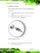
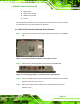
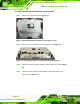
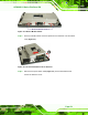
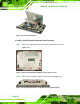
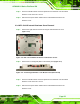
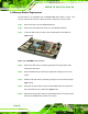
Table Of Contents
- AFOLUX LX Series Flat Panel PC
- 1 Introduction
- 2 Motherboard
- 3 Installation
- 4 System Maintenance
- 5 Award BIOS Setup
- A Safety Precautions
- B BIOS Configuration Options
- C Software Drivers
- D Watchdog Timer
- E Hazardous Materials Disclosure
- F Index
AFOLUX LX Series Flat Panel PC
Page 55
Step 3: Push the external interface connector apart from the aluminum cover and lift the
aluminum cover off the AFL-10A-LX.
Step 4: Disconnect the power switch cable from the motherboard and remove the
aluminum cover. Step 0:
4.3.4 AFL-12A-LX Internal Aluminum Cover Removal
Step 1: Remove the eight retention screws securing the internal aluminum cover
(
Figure 4-10).
Figure 4-10: AFL-12A-LX Aluminum Back Cover Retention Screws
Step 2: Remove the four hexagonal pillars on the bottom panel (
Figure 4-11).
Figure 4-11: Four Hexagonal Pillars on the Bottom Panel (AFL-12A-LX)
Step 3: Push the external interface connector apart from the aluminum cover and lift the
aluminum cover off the AFL-12A-LX.
Step 4: Disconnect the power switch cable from the motherboard and remove the
aluminum cover. Step 0: