
Manual
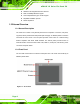
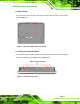
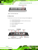
Table Of Contents
- AFOLUX LX Series Flat Panel PC
- 1 Introduction
- 2 Motherboard
- 3 Installation
- 4 System Maintenance
- 5 Award BIOS Setup
- A Safety Precautions
- B BIOS Configuration Options
- C Software Drivers
- D Watchdog Timer
- E Hazardous Materials Disclosure
- F Index
AFOLUX LX Series Flat Panel PC
Page xi
List of Figures
Figure 1-1: Front View...................................................................................................4
Figure 1-2: AFL-07A-LX/AFL-08A-LX Rear View ........................................................5
Figure 1-3: AFL-08A-LX Top View ...............................................................................5
Figure 1-4: AFL-08A-LX Side View ..............................................................................6
Figure 1-5: AFOLUX LX Series Bottom View..............................................................6
Figure 1-6: AFL-07A-LX Dimensions (units in mm).................................................13
Figure 1-7: AFL-08A-LX Dimensions (units in mm).................................................14
Figure 1-8: AFL-10A-LX Dimensions (units in mm).................................................15
Figure 1-9: AFL-12A-LX Dimensions (units in mm).................................................16
Figure 2-1: AFLMB-LX800 Connector Overview ......................................................24
Figure 3-1: Back Cover Retention Screws................................................................29
Figure 3-2: AFL-08A-LX Plastic Back Cover Removal.............................................30
Figure 3-3: CF Card Location.....................................................................................30
Figure 3-4: AFL-08A-LX Plastic Back Cover Replacement.....................................30
Figure 3-5: AFL-12A-LX Aluminum Back Cover Retention Screws .......................31
Figure 3-6: Four Hexagonal Pillars on the Bottom Panel........................................31
Figure 3-7: AFL-12A-LX HDD Bracket Retention Screws........................................32
Figure 3-8: AF-12A-LX HDD Retention Screws ........................................................32
Figure 3-9: AT/ATX Switch Location .........................................................................33
Figure 3-10: Wall-mounting Bracket..........................................................................35
Figure 3-11: Chassis Support Screws.......................................................................36
Figure 3-12: Secure the Panel PC..............................................................................37
Figure 3-13: AFL-07A-LX Panel Opening..................................................................38
Figure 3-14: AFL-08A-LX Panel Opening..................................................................38
Figure 3-15: AFL-10A-LX Panel Opening..................................................................38
Figure 3-16: AFL-12A-LX Panel Opening..................................................................39
Figure 3-17: Tighten the Panel Mounting Clamp Screws (AFL-10A/12A-LX)........40
Figure 3-18: AFL-07A-LX/AFL-08A-LX Arm Mounting Retention Screw Holes.....41