
Instruction Manual


AFOLUX LX Panel PC
Page xi
List of Figures
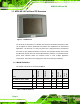
Figure 1-1: AFOLUX LX..................................................................................................................2
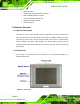
Figure 1-2: Front View....................................................................................................................4
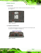
Figure 1-3: Rear View .....................................................................................................................5
Figure 1-4: Top View.......................................................................................................................5
Figure 1-5: Side View......................................................................................................................6
Figure 1-6: AFOLUX LX Bottom View...........................................................................................6
Figure 1-7: Dimensions (units in mm) ........................................................................................13
Figure 3-1: Back Cover Retention Screws .................................................................................26
Figure 3-2: CF Card Location ......................................................................................................27
Figure 3-3: AT/ATX Switch Location...........................................................................................27
Figure 3-4: Wall-mounting Bracket.............................................................................................29
Figure 3-5: Chassis Support Screws..........................................................................................30
Figure 3-6: Secure the Panel PC .................................................................................................31
Figure 3-7: Panel Opening...........................................................................................................32
Figure 3-8: Tighten the Panel Mounting Clamp Screws ...........................................................33
Figure 3-9: Arm/Stand Mounting Retention Screw Holes.........................................................34
Figure 3-10: LAN Connection......................................................................................................35
Figure 3-11: Serial Device Connector.........................................................................................36
Figure 3-12: Serial Cable Removal..............................................................................................36
Figure 3-13: RJ-45 Serial Port Pinout Location.........................................................................37
Figure 3-14: Serial Port Pinout Location....................................................................................38
Figure 3-15: USB Device Connection .........................................................................................39
Figure 4-1: Motherboard Retention Screws...............................................................................42
Figure 4-2: Aluminum Back Cover Retention Screws ..............................................................42
Figure 4-3: Two Hexagonal Pillars on the Bottom Panel..........................................................43
Figure 4-4: SO-DIMM Socket Location .......................................................................................44
Figure 4-5: DDR SO-DIMM Module Installation..........................................................................45